
LED-Microscope
This instruction outlines the process of converting a standard microscope that uses a light bulb to LED illumination. A mobile phone charger can be utilized as the power supply due to the significantly lower power consumption of LEDs. This eliminates the need for repairing or replacing defective original power supplies. Since LEDs are more durable than traditional light bulbs, they provide a reliable alternative. In many workshops, issues with broken microscope power supplies, often switch-mode types that are difficult to repair, have been encountered. Using an external standard power supply to power the light bulb is an option, but such supplies that can deliver 2 A at 12 V or 4 A at 6 V are often either unavailable or prohibitively expensive, and they lack dimming functionality. Previously, these microscopes could not be repaired. The solution lies in converting them to LED illumination. Ultra-bright white LEDs, particularly those with lenses, can match the brightness of standard 20W bulbs while consuming a fraction of the current. The current requirement is so low that common mobile phone chargers can serve as the power supply, which are inexpensive and widely available. Although high-power white LEDs may not be universally accessible yet, they are versatile and a single model can fit all microscope types and other applications, making it practical to order them from suppliers in Europe or the US. In Europe, a 1-W LED with an integrated lens costs less than 10. Ultra-bright LEDs are available in standard 5 mm housings. Using six to twelve LEDs can produce sufficient light, although six may not provide optimal uniformity. The beam angles of 15 to 30 degrees are acceptable but not ideal. LED options include 1 W, 3 W, and even 5 W types. These LEDs are mounted on small PCBs with aluminum boards, which serve as heat sinks, facilitating easy mounting and cooling. The beam angle is 110 degrees, and additional optics are required. These LEDs typically range in cost from 5 to 10. LEDs are controlled by current rather than voltage, necessitating a stable current with automatic voltage adjustment. The current stabilizer must be compatible with common mobile phone chargers, requiring a wide input voltage range of 5 to 15 V. The mobile phone charger should deliver 400 mA, which is generally standard. The specifications for a Luxeon LED indicate a requirement of 350 mA at 3.42 V. The necessary electronics must stabilize the output current at 350 mA regardless of input voltage. The circuit design is relatively simple yet requires careful consideration. Transistor T2 is responsible for controlling the LED and is connected in series with the LED and resistor R3, meaning the LED current also flows through both components. A voltage drop across the resistor is fixed at 0.7 V due to the base-emitter path of transistor T1. This fixed voltage across the resistor ensures that the current through the resistor remains constant, effectively stabilizing the current. The bias voltage for T2 is generated using a voltage divider comprising resistors R1, the potentiometer, and R2. The values of these components are not critical since the current is already limited. R2 sets the minimum brightness and ensures a smooth variation range for the potentiometer. The size of T2 is contingent upon the voltage drop across the collector-emitter junction, which is the difference between the power supply voltage and the LED voltage (3.42 V), along with the 0.7 V drop across R3. A larger transistor is required for higher power supply voltages. The power loss in the transistor is calculated as the product of the collector-emitter voltage drop and the LED current, necessitating careful selection of the transistor type to manage current and power loss effectively. Incorporating a small heat sink is advisable; directly mounting T2 to the microscope housing is even better, as it allows for effective heat dissipation.
To implement this conversion, the following components are essential: a selection of ultra-bright LEDs, a suitable mobile phone charger, a current stabilizing circuit incorporating transistors, resistors, and a potentiometer, as well as a small heat sink for thermal management. The LED arrangement should be designed to maximize light output while ensuring uniform illumination across the microscope’s field of view. Careful attention should be given to the electrical specifications of the components to ensure compatibility and reliability in operation. The resulting LED illumination system will enhance the functionality of the microscope while providing a cost-effective and durable lighting solution.This instruction shows how to convert a standard microscope with light bulb to LED light. Only a cheap mobile phone charge can be used as the power supply because of the much lower power consumption of the LED light. Defective original power supplies do not have to be repaired or exchanged. Because a LED does not break, light bulbs are no longer n eeded. In our workshop we often encountered problems with broken power supplies of microscopes. The power supplies are usually switch mode power supplies that can not be repaired easily. To supply the light bulb with an external standard power supply is an alternative but such power supplies which deliver 2 A (at 12 V) or even 4 A (at 6 V) are either not available or too expensive, and a dim function is still missing. In the past these microscopes could not be repaired. The solution is to convert these microscopes to LED illumination. White ultra-bright LEDs, especially with a lens, are as bright as common 20W-bulbs, but they only need a fraction of the current.
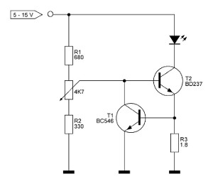
The current needed is so small that common mobile phone chargers can be used as a power supply. Mobile phone chargers are very cheap and commonly available. I admit a white high-power-LED is not (yet) available everywhere. But because they are universal in the usage and only one model fits for all microscope types (and for other purposes) it make sense to order some pieces from Europe or US. In Europe a 1-W LED with integrated lens is less than 10. Ultra-bright LEDs are available in standard 5 mm housings (No. 1). Six to twelve LEDs produce a light which is bright enough (No. 2). But the illumination with just six LEDs could be more homogeneous. The beam angle of 15 -30 ° is not perfect but acceptable. One LED costs 1 W, 3 W and even 5 W-types exist. The LED is mounted on a small PCB with an aluminium board. The aluminium acts as a heat sink. This make mounting and cooling easy. The beam angle is 110 °. An additional optic has to be used. Such LEDs cost 5 - 10. LEDs are controlled by the current and not by the voltage. The current has to be stable and the voltage will be adjusted automatic. This current stabilizer must run with any common mobile phone chargers. That means a wide-range voltage input of 5 - 15 V is demanded. The mobile phone charger has to deliver 400 mA which is always the case. The specifications of a Luxeon LED are: 350 mA at 3. 42 V. The needed electronics has to stabilize the output current to 350 mA whatever the input voltage is. The circuit is quite simple but tricky. Transistor T2 controls the LED. Together with R3 it is in series with the LED. That means that the LED current also flows through the transistor and the resistor. Parallel to the resistor is the BE path of the transistor T1. Because the BE-voltage drop of a transistor is always 0. 7 V also the voltage across the resistor is fixed to 0. 7 V. But when the voltage across the resistor is fixed and the resistor anyway then also the current through the resistor must be fixed.
The current is stabilized. The bias voltage for T2 is created by the voltage divider R1, the pot and R2. The values are uncritical because the current is already limited. R2 is responsible for the lowest brightness and ensures that the pot has a nice variation range. T2 must be a bigger one. The size of T2 depends on the voltage drop across CE. It is the difference between the power supply voltage and the LED voltage (3. 42 V) and the 0. 7 V voltage drop across R3. T2 has to be bigger, the higher the power supply voltage is. The transistor voltage drop V(CE) multiplied by the LED current makes the transistor power loss. Current and power loss have to be considered when choosing the transistor type. A small heat sink is never wrong. In this case mounting T2 directly to the housing of the microscope is even a better idea. The heat can be conducted away over the housing and the other devices can be mounted directly 🔗 External reference
To implement this conversion, the following components are essential: a selection of ultra-bright LEDs, a suitable mobile phone charger, a current stabilizing circuit incorporating transistors, resistors, and a potentiometer, as well as a small heat sink for thermal management. The LED arrangement should be designed to maximize light output while ensuring uniform illumination across the microscope’s field of view. Careful attention should be given to the electrical specifications of the components to ensure compatibility and reliability in operation. The resulting LED illumination system will enhance the functionality of the microscope while providing a cost-effective and durable lighting solution.This instruction shows how to convert a standard microscope with light bulb to LED light. Only a cheap mobile phone charge can be used as the power supply because of the much lower power consumption of the LED light. Defective original power supplies do not have to be repaired or exchanged. Because a LED does not break, light bulbs are no longer n eeded. In our workshop we often encountered problems with broken power supplies of microscopes. The power supplies are usually switch mode power supplies that can not be repaired easily. To supply the light bulb with an external standard power supply is an alternative but such power supplies which deliver 2 A (at 12 V) or even 4 A (at 6 V) are either not available or too expensive, and a dim function is still missing. In the past these microscopes could not be repaired. The solution is to convert these microscopes to LED illumination. White ultra-bright LEDs, especially with a lens, are as bright as common 20W-bulbs, but they only need a fraction of the current.
The current needed is so small that common mobile phone chargers can be used as a power supply. Mobile phone chargers are very cheap and commonly available. I admit a white high-power-LED is not (yet) available everywhere. But because they are universal in the usage and only one model fits for all microscope types (and for other purposes) it make sense to order some pieces from Europe or US. In Europe a 1-W LED with integrated lens is less than 10. Ultra-bright LEDs are available in standard 5 mm housings (No. 1). Six to twelve LEDs produce a light which is bright enough (No. 2). But the illumination with just six LEDs could be more homogeneous. The beam angle of 15 -30 ° is not perfect but acceptable. One LED costs 1 W, 3 W and even 5 W-types exist. The LED is mounted on a small PCB with an aluminium board. The aluminium acts as a heat sink. This make mounting and cooling easy. The beam angle is 110 °. An additional optic has to be used. Such LEDs cost 5 - 10. LEDs are controlled by the current and not by the voltage. The current has to be stable and the voltage will be adjusted automatic. This current stabilizer must run with any common mobile phone chargers. That means a wide-range voltage input of 5 - 15 V is demanded. The mobile phone charger has to deliver 400 mA which is always the case. The specifications of a Luxeon LED are: 350 mA at 3. 42 V. The needed electronics has to stabilize the output current to 350 mA whatever the input voltage is. The circuit is quite simple but tricky. Transistor T2 controls the LED. Together with R3 it is in series with the LED. That means that the LED current also flows through the transistor and the resistor. Parallel to the resistor is the BE path of the transistor T1. Because the BE-voltage drop of a transistor is always 0. 7 V also the voltage across the resistor is fixed to 0. 7 V. But when the voltage across the resistor is fixed and the resistor anyway then also the current through the resistor must be fixed.
The current is stabilized. The bias voltage for T2 is created by the voltage divider R1, the pot and R2. The values are uncritical because the current is already limited. R2 is responsible for the lowest brightness and ensures that the pot has a nice variation range. T2 must be a bigger one. The size of T2 depends on the voltage drop across CE. It is the difference between the power supply voltage and the LED voltage (3. 42 V) and the 0. 7 V voltage drop across R3. T2 has to be bigger, the higher the power supply voltage is. The transistor voltage drop V(CE) multiplied by the LED current makes the transistor power loss. Current and power loss have to be considered when choosing the transistor type. A small heat sink is never wrong. In this case mounting T2 directly to the housing of the microscope is even a better idea. The heat can be conducted away over the housing and the other devices can be mounted directly 🔗 External reference