
LED TesterCircuit

The LED tester circuit serves as an essential tool for validating the functionality of LEDs before incorporating them into electronic projects. The circuit design is straightforward, allowing for a compact and efficient testing solution. The use of FET T1 as a constant current source ensures that the test current remains stable, which is crucial for accurate brightness assessment across different LED types. By integrating Zener diodes, the circuit not only provides a means to test multiple LEDs simultaneously but also protects against potential damage from reverse polarity connections, which can occur when handling used components.
The flexibility of the circuit is enhanced by the ability to adjust the test current via potentiometer P1. This feature allows users to tailor the testing conditions based on the specific LED characteristics, ensuring optimal performance during testing. The inclusion of an IC socket as a test interface simplifies the process of swapping LEDs, making it user-friendly and efficient for rapid testing scenarios.
When expanding the circuit to accommodate additional LEDs, careful consideration must be given to the choice of Zener diodes, particularly when testing LEDs with higher forward voltage requirements, such as blue and white LEDs. The circuit's design allows for scalability, making it suitable for various applications, from hobbyist projects to more advanced electronic designs.
In summary, this LED tester circuit is a versatile and practical solution for assessing LED functionality, ensuring that only fully operational LEDs are utilized in final applications. The thoughtful design elements, such as constant current regulation and easy LED replacement, contribute to its effectiveness and user-friendliness.Before you use LEDs, it`s a good idea to check them out. With a LED tester, you can even do it in the dark! LEDs are available nowadays in all shapes and colors. There are types with clear, colorless packages, while others have colored plastic packages. Many modern types of LEDs need less current than older types. Some of them provide quite a puddle of light if you give them a decent amount of current. When you`re working with used LEDs from the junk box, there`s a good chance that you can`t tell which lead is which any more. (If the leads haven`t been trimmed, the short lead is always the cathode lead and the long lead is the anode lead.
) If you use several LEDs in a display where they all have the same current you naturally want all the LEDs to have the same brightness. But that`s not always the case, even with LEDs of the same type. To save yourself unnecessary soldering work, it`s a good idea to check the LEDs out first. That`s the job of the LED tester described here. This circuit can be used to test up to three LEDs at once, connected in series. You can easily increase that number by using a higher supply voltage. If you do so, you should allow 2. 7 V for each additional LED. The Zener diodes are included in the circuit so it can also be used to test one or two LEDs. Another benefit of the Zeners is that even if one or more of the LEDs are defective or connected with reverse polarity, the remaining ones will light up normally.
That makes it easy to spot suspect LEDs. If you extend the tester to handle more LEDs, you must add another Zener diode for each LED position. The test current that ows through the LEDs is held reasonably constant by FET T1, independent of the number of LEDs being tested.
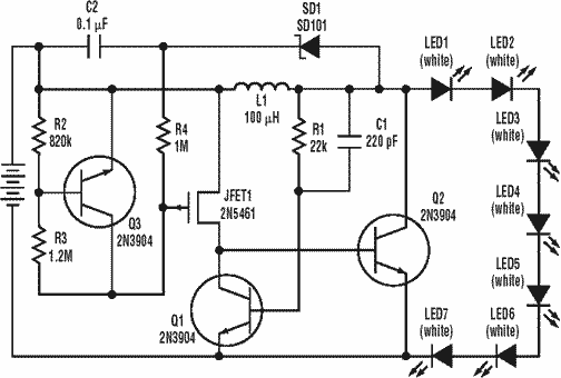
The FET is used as a constant-current source to keep the circuit as simple as possible. The drawback of this approach is that the tolerance range of FET characteristics is especially large. The type used here even has three versions: A, B and C. We used the B version here so the current through the LEDs can be adjusted using potentiometer P1 over the range of 1 7 mA.
If you need more current, you can use a BF254C instead, but then you will also need a higher supply voltage. For example, you can connect two 9-V batteries in series or power the circuit from a mains adapter. However, some LEDs have a maximum rated current of only 5 mA. You should thus always start testing at the lowest current by setting P1 to maximum resistance. You can easily see from the brightness whether you need more current. If an LED does not light up, it may be defective or connected the wrong way round. Reduce the current to the minimum level before reversing or replacing any LEDs. If you label the polarity of the terminals on the LED tester, you can easily mark the cathode and anode leads of the tested LEDs.
To make it easy to swap the LEDs, you can use an IC socket as a test socket. The selected Zener diodes were chosen to make the tester suitable for red, yellow and green LEDs. Red LEDs have a forward voltage of 1. 6 V to 1. 8 V. The value for yellow LEDs is around 1. 9 V, and with green LEDs the forward voltage can be as high as 2 V. If you also want to test modern blue or white LEDs, you will have to replace the Zener diodes with types having a voltage of 4. 7 V or 5. 1 V. The supply voltage will also have to be increased accordingly for example, by connecting two 9-V batteries in series.
🔗 External reference
Related Circuits
The object of Quick Draw is to test your reaction time against your opponent's. A third person acts as a referee and begins the duel by pressing S1, which lights LED1. Upon seeing LED1 go on, you try to...
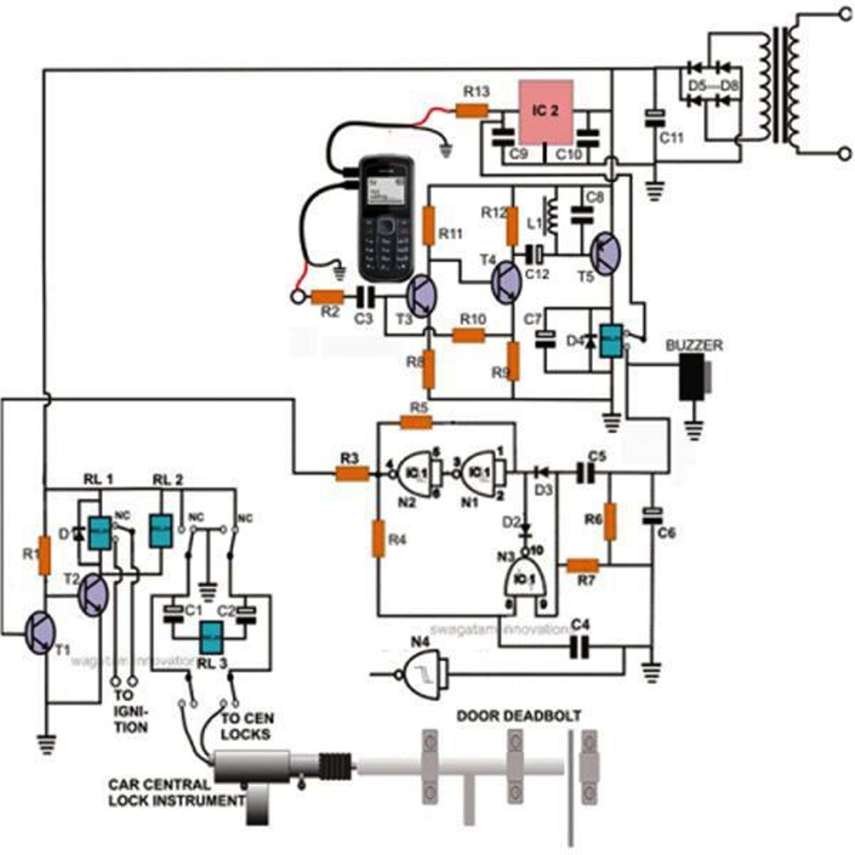
Controlling a door lock through a personal cell phone has become remarkably straightforward. This project outlines the construction of a simple electronic circuit that transforms a conventional door lock into a high-security lock, which can now be operated via...
A low power, long-life LED flashlight circuit. Electronic Design proposed a simple circuit to resolve this in a recent article. The front end of their circuit draws less than a milliamp of extra current. The described LED flashlight circuit is...
Described here is a very inexpensive solution to many phono-controlled applications like remote switching on, for instance, or activating a camera, tape recorder, burglar alarms, toys, etc. The circuit given here employs a condenser microphone as the pick-up. A...
Acoustic check of transistor and diode junctions. Also suitable as a continuity tester. Short circuits or broken PCB tracks can be easily recognized. The acoustic check of transistor and diode junctions is a method used to assess the functionality of...
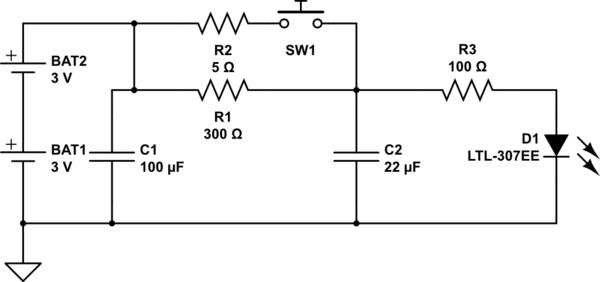
The circuit operates as follows: The LED is typically powered at a low brightness through resistors R1 and R3. SW1 functions as a spring and wire-based accelerometer. When SW1 is activated, capacitor C2 charges rapidly at a rate determined...