
LED VoltMeter Circuit

The LED voltmeter circuit comprises a series of components designed to accurately reflect the state of the battery charge. The primary components include four Zener diodes, each selected to correspond to specific voltage levels indicative of the battery's charge status. These Zener diodes are connected in parallel with the LEDs, ensuring that each LED illuminates when the voltage across the diode exceeds its breakdown voltage.
The Zener diodes are chosen based on the desired voltage thresholds: for instance, a 13.6V Zener diode will activate the first LED when the battery voltage is at or above this level. The subsequent Zener diodes could be rated at 14.0V, 14.4V, and 14.8V to correspond with increasing battery voltages, thus illuminating additional LEDs as the battery approaches a fully charged state.
The circuit may also incorporate a resistor in series with each LED to limit current and prevent damage. The resistors are calculated based on the forward voltage drop of the LEDs and the supply voltage to ensure proper operation.
In cases where the battery voltage falls below 10.6 volts, a cutoff mechanism can be included to prevent any LED from lighting up, indicating a critically low charge. This feature is essential for protecting battery health and preventing deep discharge.
The overall design is straightforward, allowing for easy assembly and integration into battery monitoring systems. The LED voltmeter serves as a visual indicator, providing immediate feedback on the battery's state of charge and facilitating timely maintenance or recharging actions as necessary.A Simple LED Voltmeter to Monitor the charge level in Lead Acid Battery or Tubular battery. The terminal voltage of the battery is indicated through a four level LED indicators. The nominal terminal voltage of a Lead Acid battery is 13. 8 volts and that of a Tubular battery is 14. 8 volts when fully charged. The LED voltmeter uses four Zener diodes to light the LEDs at the precise breakdown voltage of the Zener diodes. Usually the Zener diode requires 1. 6 volts in excess than its prescribed value to reach the breakdown threshold level. When the battery holds 13. 6 volts or more, all the Zener breakdown and all LEDs light up. When the battery is discharged below 10. 6 volts, all the LEDs remain dark. So depending on the terminal voltage of the battery, LEDs light up one by one or turns off. 🔗 External reference
Related Circuits
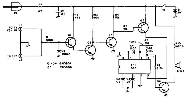
For use with low-power transmitters that require a positive keying voltage. The transistors Q1, Q2, and Q3 are configured as a switching amplifier. When the key is pressed, the collector of Q3 is pulled to ground, which activates Q5...
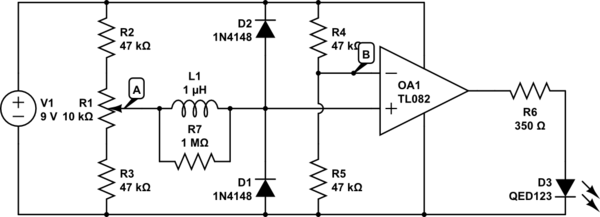
The circuit above is a canonical AC coupled common emitter amplifier, which is typically used as a linear amplifier rather than a switch that activates when the input exceeds a certain level. The AC coupled common emitter amplifier is...
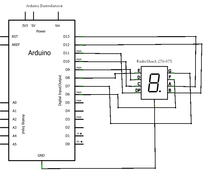
If you're not familiar with the Arduino, it is an open-source electronics prototyping platform based on flexible, easy-to-use hardware and software. It has a small microcontroller, a USB port to connect to your computer for programming, a power socket...
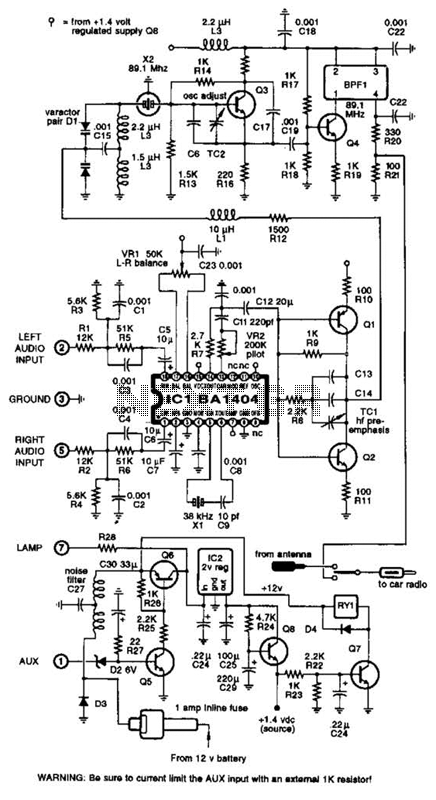
A BA1404 integrated circuit (IC) is utilized to generate a complete FM multiplex (MPX) signal. The chip incorporates all necessary circuitry. Components CI, R3, R4, and C4 are responsible for providing pre-emphasis. The transmitter operates on a single AA...
This power supply was designed for use with the Simple hybrid amplifier published elsewhere in this issue. It is suitable for various applications as well. A cascade generator is utilized for the 170 V output, a switch-mode supply provides...
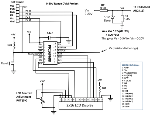
This project details the construction of a digital voltmeter utilizing a PIC microcontroller. A character-based HD44780 LCD display is employed to visualize voltage measurements. The microcontroller selected for this project is the PIC16F688, which features 12 I/O pins, with...
Warning: include(partials/cookie-banner.php): Failed to open stream: Permission denied in /var/www/html/nextgr/view-circuit.php on line 713
Warning: include(): Failed opening 'partials/cookie-banner.php' for inclusion (include_path='.:/usr/share/php') in /var/www/html/nextgr/view-circuit.php on line 713