
LEDs or Lamps Sequencer
This circuit implements a sequential LED or lamp illumination system, characterized by its modular design and flexibility. The basic operational principle involves a series of stages, each consisting of a small circuit dedicated to an individual LED or lamp. The sequential nature of the illumination is achieved by connecting the output of the final stage back to the input of the first stage, forming a feedback loop that allows for continuous operation.
The P1 pushbutton serves a dual purpose: it initiates the sequence upon power-on and provides a method for controlling the illumination of multiple devices simultaneously. This functionality is particularly useful in scenarios where a lengthy sequence is desired, as it allows for the selection of specific devices to remain illuminated while others are turned off. The requirement to hold P1 closed until a designated LED or lamp is illuminated ensures that the circuit is properly initialized before the sequencer begins its operation.
The design accommodates various voltage levels, with the maximum permissible input being 24V. This allows for a higher number of LEDs to be connected in series, optimizing the circuit for different applications. The use of BC337 transistors is suitable for standard current loads; however, for higher current demands exceeding 400mA, the circuit can be upgraded by substituting these transistors with more robust Darlington types, ensuring reliability and performance under increased load conditions.
This modern iteration of the circuit, leveraging advancements in semiconductor technology, offers enhanced efficiency and performance compared to earlier designs that utilized germanium transistors and low voltage lamps. The incorporation of silicon transistors and LEDs represents a significant step forward, providing a more durable and energy-efficient solution for sequential lighting applications.The purpose of this circuit was to create a ring in which LEDs or Lamps illuminate sequentially. Its main feature is a high versatility: you can build a loop containing any number of LEDs or Lamps, as each illuminating device has its own small circuit. The diagrams show three-stage circuits for simplicity: you can add an unlimited number of stages (shown in dashed boxes), provided the last stage output was returned to the first stage input, as shown. P1 pushbutton purpose is to allow a sure start of the sequence at power-on but, when a high number of stages is used, it also allows illumination of more than one LED or Lamp at a time, e.
g. one device illuminated and three out and so on. After power-on, P1 should be held closed until only the LED or Lamp related to the module to which the pushbutton is connected remains steady illuminated. When P1 is released the sequencer starts: if P1 is pushed briefly after the sequence is started, several types of sequence can be obtained, depending from the total number of stages.
* Using 24V supply (the maximum permitted voltage), about 10 LEDs wired in series can be connected to each module, about 7 at 15V and no more than 5 at 12V. * If you intend to use lamps drawing more than 400mA current, BC337 transistors should be substituted by Darlington types like BD677, BD679, BD681, 2N6037, 2N6038, 2N6039 etc.
* A similar design appeared in print about forty years ago. It used germanium transistors and low voltage lamps. I think the use of LEDs, silicon transistors, Darlington transistors and 24V supply an interesting improvement. 🔗 External reference
Related Circuits
A 10-light LED bar graph is desired, where the LEDs light up sequentially until all are lit, then cycle back down until all are off. The LM3914 - Dot/Bar Display Driver is a simpler analog solution that operates in...
The following circuit illustrates a Dancing LEDs electronic circuit diagram. This circuit is based on the LM358 integrated circuit. Features: IC1A amplifies the signal. The Dancing LEDs circuit utilizes the LM358 operational amplifier to create a visually appealing light display....
The 555 timer IC is connected for Astable Operation, the clock pulses are fed to the 4017 IC via the 10K resistor. The 4017 is a 10 stage counter, therefore the sequence of the traffic lights is spread over...

The drawing below illustrates a multistage light sequencer using discrete parts and no integrated circuits. The idea is not new and I hear a similar circuit was developed about 40 years ago using germanium transistors. The idea is to...
The ADRF6702 TxMod is an IQ modulator that includes an integrated phase-locked loop (PLL) and voltage-controlled oscillator (VCO). The PLL synthesizer employs a fractional-N PLL to produce a 2*FLO input for the I-Q modulator. The PLL reference input can...
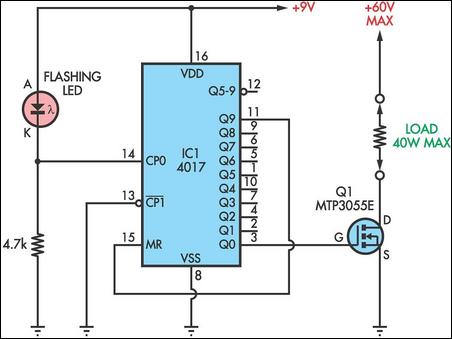
This circuit utilizes a flashing LED as the clock input for a 4017 decade counter. Typical flashing LEDs, such as the DSE cat Z-4044, flash at approximately 2Hz, causing the outputs Q0-Q9 to cycle at that rate. For instance,...
Warning: include(partials/cookie-banner.php): Failed to open stream: Permission denied in /var/www/html/nextgr/view-circuit.php on line 713
Warning: include(): Failed opening 'partials/cookie-banner.php' for inclusion (include_path='.:/usr/share/php') in /var/www/html/nextgr/view-circuit.php on line 713