
LES production with automatic hand controller circuit

The described circuit is a simple yet effective hand detection system that utilizes infrared technology for controlling a heating and cooling fan. The circuit includes key components such as an infrared light-emitting diode (VD1) and an infrared receiver diode (VD2), which work together to detect the presence of a hand. The operation begins with VD1 continuously emitting infrared light. When a hand is placed within the detection range, it obstructs the infrared beam, leading to a significant increase in the resistance of VD2. This change in resistance is critical as it alters the voltage signal sent to the LSE pin.
The LSE pin serves as a control signal that determines the state of the transistor (VT). Under normal conditions, when the infrared beam is uninterrupted, the LSE pin outputs a high signal, keeping the transistor in the off state. This prevents the relay (J) from activating, thereby ensuring that the heating and cooling fan remains powered off. The relay's contacts j1-1 and j1-2 are open, effectively isolating the fan from the power source.
Upon hand detection, the increased resistance at VD2 causes the LSE pin to output a low signal. This transition triggers the transistor VT to turn on, allowing current to flow through the relay coil. As a result, the relay engages, closing its contacts and supplying power to the heating and cooling fan. This action activates the fan, providing the desired airflow for drying hands or cooling.
The system is designed for ease of use, with the heating and cooling fan needing to be connected to the power grid prior to operation. The user can initiate the fan function by pressing the "hot air" switch, which may also serve to indicate that the system is ready to operate. Overall, this infrared-based circuit provides a reliable and efficient means of controlling a fan in response to user interaction, enhancing convenience and hygiene in settings such as public restrooms or food preparation areas.Circuit operation principle of the device shown in Figure. Usually infrared light emitting tube VD1 infrared radiation emitted in infrared receiver tube VD2, leading to VD2 internal resistance becomes smaller, so the LSE feet high output at this time, when the transistor VT end, the relay J is released, it often open contact j1-1, j1-2 off, heating and cooling fan does not work without power. When people washing hands, to put his hand between VD1 and VD1, blocking the infrared emitted by the VD1, VD2 of resistance increases at this time, the equivalent of LSE O, feet open, so the LSE pin output low level, the transistor VT conduction, the relay J excitation pull its power contacts.
Heating and cooling fan should be pre-connected to the grid, the press of "hot air" and switch on the machine.
Related Circuits
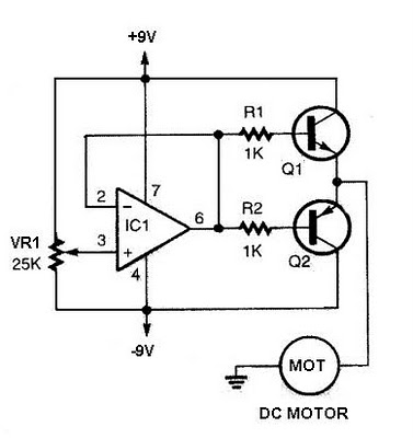
The speed increases in either direction as the potentiometer VR1 is adjusted toward its ends. The TIP3055 Q1 NPN power transistor has a collector current specification of 15A and a VCE0 rating of 60V DC. The MJE34 Q2 PNP...
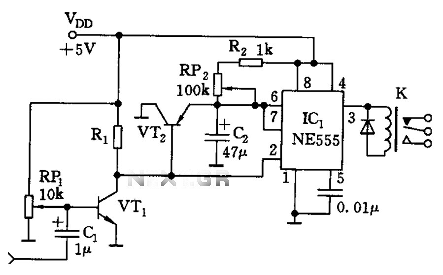
The circuit consists of a sound detection circuit and a monostable trigger circuit that activates a relay. VT1 amplifies the input audio signal. When a signal is detected, the 555 timer is triggered, pulling K. Simultaneously, VT2 conducts, allowing...
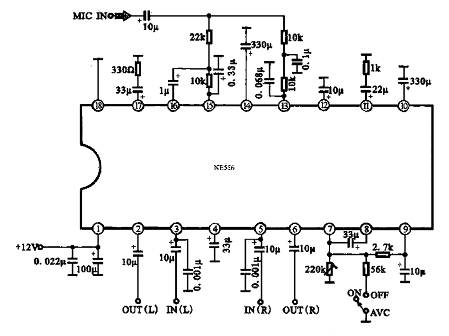
Automatic volume adjustment with ambient noise control circuit. In car stereos and similar devices, the ambient noise level varies during high-speed and low-speed driving or while stationary, leading to different volume requirements. A fixed volume adjustment method may negatively...
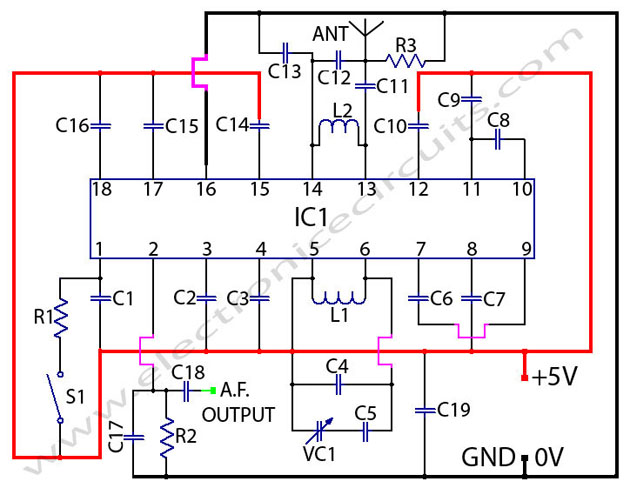
TDA7000 FM Radio Receiver Circuit Using Tuning Capacitor GENERAL DESCRIPTION The TDA7000 is a monolithic integrated circuit for mono FM. The TDA7000 is designed as a complete FM radio receiver circuit, integrating all necessary functions for receiving mono FM signals....
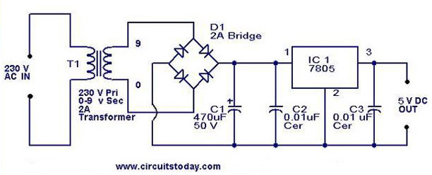
A 5V power supply using IC 7805 is designed and explained with a neat circuit diagram. The circuit for a 5V power supply utilizing the IC 7805 voltage regulator is a straightforward and efficient design that provides a stable output...
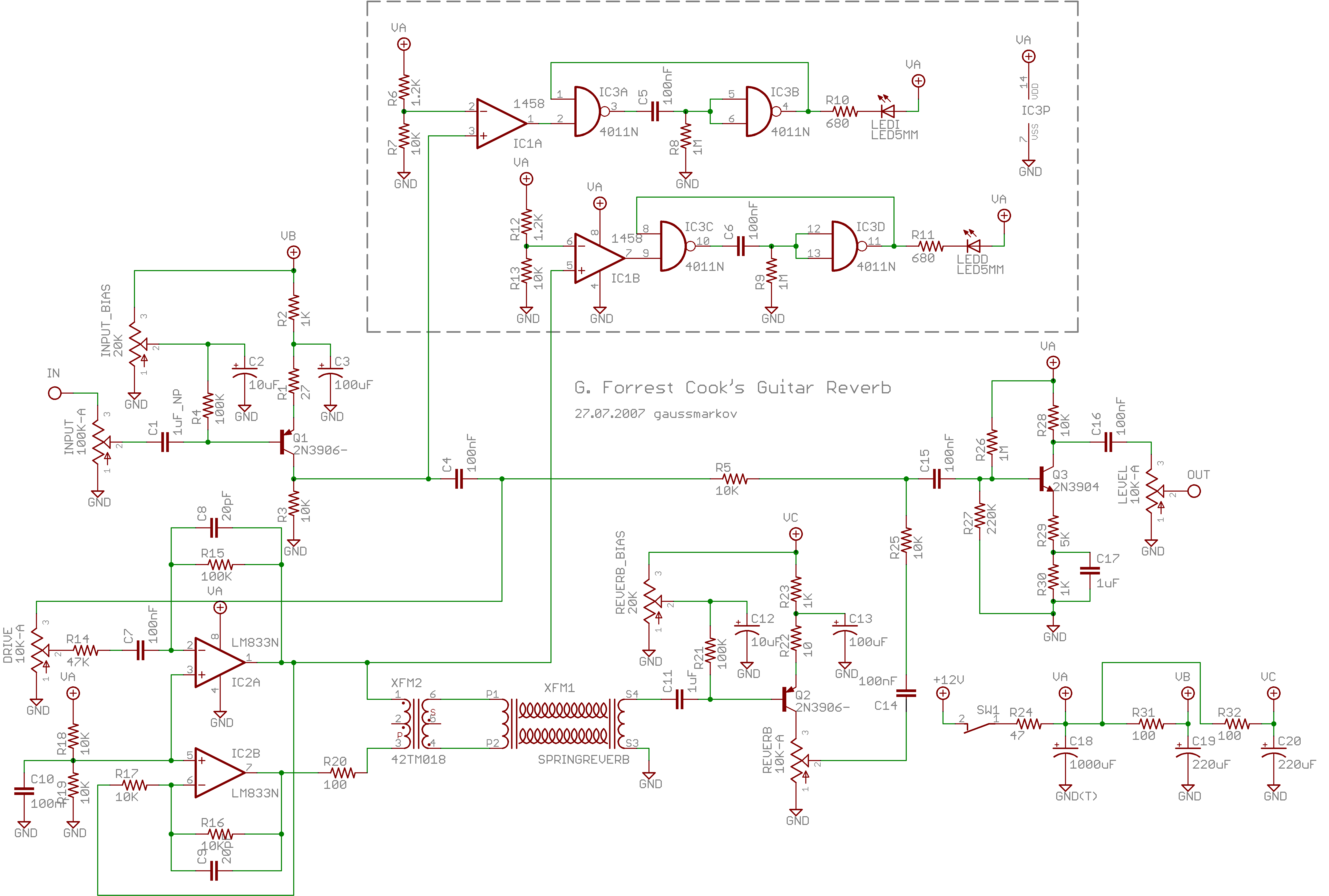
Spring reverb produces a clean and natural sound, often perceived as exceptionally good for a spring reverb. However, when the reverb springs are struck forcefully, they create explosive dub-like effects. Spring reverb is an analog sound processing technique that utilizes...