
Lie Detector Circuit

The electronic lie detector circuit operates on the principles of galvanic skin response (GSR) and heart rate monitoring to assess physiological changes in the subject's body. The circuit typically consists of a microcontroller, sensors, and a display unit.
The GSR sensor measures the electrical conductance of the skin, which varies with moisture levels influenced by sweat gland activity. This response is often heightened during stressful situations, such as when a person is lying. The heart rate sensor, usually an optical sensor, detects changes in blood flow and pulse rate, which can also indicate emotional distress.
The microcontroller processes the signals from both sensors, analyzing the data to produce two distinct outputs. The first output represents the subject's response to difficult questions, while the second output reflects their emotional state, providing insights into their honesty or stress levels during the interrogation.
The circuit can be designed with an LCD or LED display to visualize the readings in real-time. Power supply considerations are essential, as the circuit may require a stable voltage source to ensure accurate sensor readings. Additionally, calibration of the sensors is necessary to account for individual differences in baseline physiological responses.
Overall, this electronic lie detector circuit serves as a tool for understanding human emotions and truthfulness through measurable physiological responses.This electronic lie detector circuit project will give two readings: one for difficult questions for the subject and another to show its emotional state in.. 🔗 External reference
Related Circuits

An A/D conversion circuit is designed to convert analog voltage into a digital signal encoding circuit. It utilizes ADC0808/ADC0809 circuit chips, which can convert analog signals into an 8-bit digital output signal. The A/D conversion circuit employs the ADC0808 or...
This text outlines preliminary plans for a frequency meter designed for a bat detector. The device measures the frequency of the local oscillator in a heterodyne type bat detector, serving as a valuable tool for bat identification. The frequency...
In a servo system, the current drive connection is frequently utilized. The output current (IOUT) is proportional to the input channel number (y). Using the current drive mode can mitigate issues caused by the motor's large inductance, which induces...
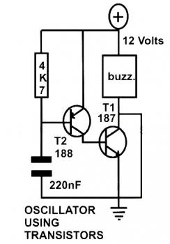
This schematic diagram represents a basic oscillator circuit utilizing two transistors. When the transistors and several passive components are connected as illustrated, the circuit begins to oscillate. The oscillation frequency can be modified by altering the values of either...

The DC output of the voltage multiplier ranges from 1,000 volts to 30,000 volts, with the actual voltage depending on the size of the cathode ray tube (CRT) and its application. Voltage multipliers can also serve as primary power...
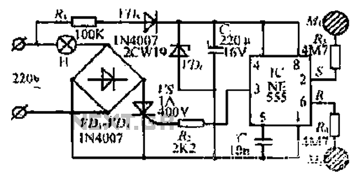
220V AC by Ri buck, Diao. C1 chain ferry flood ear, shouted for the regulator to 12V make C collapse. The film hand touch under ridicule the MT electrode films, clutter body. More: induction signal sent by See Cutting...