
light activated led
The light-activated LED circuit provides an excellent introduction to basic electronics and the principles of light sensing. The photoresistor, also known as a light-dependent resistor (LDR), changes its resistance based on the intensity of light falling on it. In low light conditions, the resistance of the photoresistor is high, which limits the current flowing through the circuit. Conversely, when light is detected, the resistance decreases, allowing more current to flow through the circuit.
The 2N2222 transistor serves as a switch that controls the LED. When the photoresistor detects sufficient light, the voltage at the base of the transistor rises, turning it on and allowing current to flow from the collector to the emitter, thereby lighting the LED. The variable resistor (VR) allows for fine-tuning of the light sensitivity threshold, enabling the user to set the desired light level at which the LED will activate.
The inclusion of a 1K resistor in series with the photoresistor is crucial for protecting the component from excessive current, especially when the variable resistor is set to its lowest value. The 330-ohm resistor connected in series with the LED limits the current flowing through the LED to a safe level, preventing potential damage due to overcurrent.
Powering the circuit with four 1.5V batteries provides a total voltage of 6V, suitable for the operation of the circuit components, including the transistor and LED. This configuration allows for flexibility in battery selection, as any combination of AA or AAA batteries can be utilized.
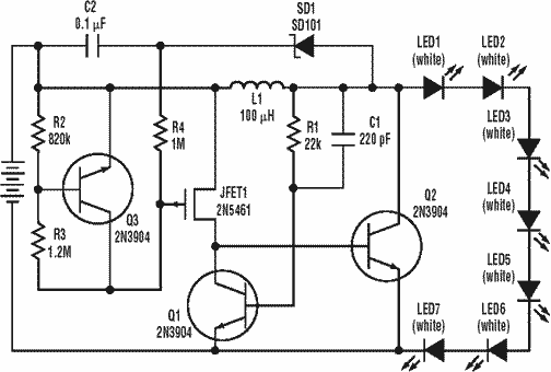
Overall, this light-activated LED circuit is not only simple to build but also serves as an educational tool for understanding the interaction between light sensors and electronic switches. It is a practical demonstration of how light can control electrical devices, making it an ideal project for beginners in electronics.A simple and interesting project of a light activated LED circuit, which will light up an LED when receives light. The circuit is very easy to build and using only six components. The photoresistor is performing the light sensing task. The transistor 2N2222 is working as a switch in this circuit. When any type of light like sunlight, bulb or lamp light will fall on the surface of photoresistor it will switch on the transistor and the LED will lightup. The 50K variable resistor (VR) is used to adjust the amount of light on which you want to lightup the LED.
The 1K resistor is used to protect the photoresistor from direct connecting to the supply when the variable resistor is on zero and 330 ohms resistor is used for providing the required current to the LED. The circuit can be operated with four 1. 5V batteries of any size. 🔗 External reference
Related Circuits
This little circuit can be used to dim lights up to about 350 watts. It uses a simple, standard TRIAC circuit that generates very little heat. Please note that this circuit cannot be used with fluorescent lights. This circuit...
A low power, long-life LED flashlight circuit. Electronic Design proposed a simple circuit to resolve this in a recent article. The front end of their circuit draws less than a milliamp of extra current. The described LED flashlight circuit is...
Light flashing circuit. This circuit is designed to create a small lamp that flashes with a signal at a rate of one flash per second, controlled by adjusting the lamp voltage through resistor R1. The rate is adjustable to...
Replacing the resistor/transistor with an n-channel power MOSFET and substituting the relay/protection diode with a light bulb results in a simplified circuit that mirrors the original design, provided one end of the light bulb is connected to +12V. If...
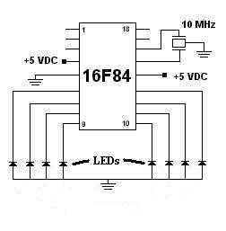
This was my first successful project with a PIC chip. I used a 16F84 with a 10MHz resonator with built-in caps. Click here to view the source code to this project. The code is written in Hi-Tech C. Click...
Circuit schematics for the 555-based PLL laser light PFM receiver. Although R4 is shown as a resistor, it is advisable to replace it with a 10-kΩ precision potentiometer to allow for fine-tuning of the transmitter's center frequency. Experimentation with...