
light bulb pcr
The Light Bulb PCR machine is an innovative approach to polymerase chain reaction (PCR) technology, utilizing readily available components to create a functional and efficient system. The design leverages a light bulb, specifically a 150 Watt incandescent bulb, which provides the necessary heat for denaturation and annealing steps in the PCR process. The choice of an old computer fan for cooling is an economical solution that ensures rapid temperature changes between cycles, essential for the amplification process.
The use of an Arduino Uno as the central control unit allows for flexibility in programming and monitoring the PCR cycles. The relay interface provides a safe and effective way to control the high-voltage light bulb, ensuring that the Arduino can operate without direct exposure to high voltages. The integration of the Maker Shield simplifies the wiring and control of multiple relays, enhancing the overall reliability of the system.
The thermistor's role in temperature monitoring is critical, as accurate temperature readings are essential for successful PCR. The placement of the thermistor within the tube holes ensures that it accurately reflects the temperature of the samples being processed. This feedback loop allows the Arduino to adjust the heating element dynamically, maintaining optimal temperatures throughout the PCR cycles.
The structural design of the PCR machine, using 4-inch PVC pipe, not only provides a robust and stable framework but also allows for easy modifications and upgrades. The three-layer construction enables efficient organization of components, with the top layer facilitating sample placement, the middle layer housing the heating and cooling elements, and the bottom layer protecting the control circuitry.
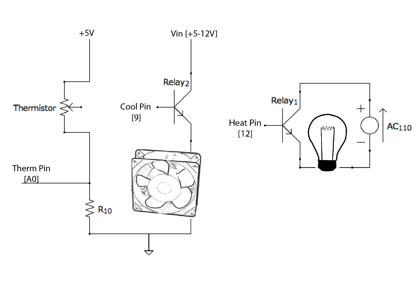
In summary, the Light Bulb PCR machine represents a practical and cost-effective solution for conducting PCR experiments, suitable for educational purposes or small-scale research applications. Its design emphasizes ease of use, safety, and adaptability, making it an excellent choice for those interested in exploring PCR technology without the need for expensive commercial equipment.Based on this `manual` PCR machine I built a few weeks ago, the Light Bulb PCR machine uses a light bulb and an old computer fan as its heating and cooling elements: Instead of the switches pictured above, the unit is now controlled by an Arduino Uno, Code Available Here. It uses a thermistor (a resistor that allows more current to flow the more heat is available) to monitor the temperature of the samples. Here`s the schematic: The light bulb is run on 110 Volt AC, so the Arduino controls a relay which turns the lamp circuit on and off. Both the Arduino and Fan can be powered by USB or by a 12 V external power supply (which provides faster cooling rates).
I was able to put both of the relay systems onto the Maker Shield (which is awesome by the way, if you arduino you should look into getting one). This is what it ended up looking like: In this model, the tubes are heated using a 150 Watt light bulb (though you could definitely go with lower wattage) and cooled simply by an old computer fan I had lying around from one of many PC cannibalizations.
The timing of the machine is actually pretty solid - a 1 minute elongation with 25 cycles ends up being ~2. 25 hours. I`ll get ramp rates posted soon. I built this prototype out of 4`` PVC pipe for a few reasons: because there are many prefabricated attachments available, it`s easily available and has consistent diameter and because I have quite a bit of experience working with it.
There are three layers in the system all based on one 4`` PVC coupling and held together with regular 4`` pipe. The top layer is concave and holds the tubes and thermistor near the light bulb. The middle layer holds the fan and light bulb in place. The bottom layer encases the control system and safety switch in case something starts to smell. smoky. The temperature is monitored using a thermistor - basically a resistor that decreases resistance the hotter it gets.
The way I have it wired, the hotter the thermistor gets, the more potential feeds into the analog input pin on the arduino. The thermistor is placed inside one of the tube holes on the top unit. I still run the machine using my laptop and the arduino serial monitor, but it can work as a standalone device if you don`t want to monitor the cycles.
The arduino can be powered from the USB port while the lamp circuit needs to be plugged in to a 110 outlet. 🔗 External reference
Related Circuits
The title contains numerous words because this instructable integrates various concepts from multiple sources. The primary idea originated from Robomaniac's Desktop Energy Seed Lamp, combined with Witch's Growing Plants with LED Lights instructable and various wick gardening planters. The...

A simple light-activated switch circuit with a diagram and schematic using IC LM311 wired as a voltage comparator and an LDR that acts as a light sensor. The described circuit utilizes the LM311 integrated circuit, which functions as a voltage...
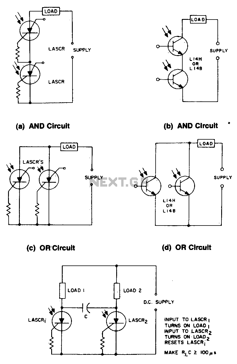
These circuits illustrate some of the common logic functions that can be implemented. The provided circuits serve as examples of fundamental logic functions utilized in digital electronics. Logic functions are the building blocks of digital systems, enabling the execution of...

Cl, VDI, VD2, C2 form a simple capacitive step-down voltage regulator circuit with a rectifier output providing approximately 8V DC voltage for the LM567. A 5.6-foot manifold is connected. Resistors R3, RP, and capacitor C3 create an ultra-low frequency...
The objective of this project is to create a controller-based model that counts the number of individuals entering a specific room and activates the lighting accordingly. This is achieved through the use of sensors that detect the current number...
If the light in a seldom-used room, such as a loft, is forgotten and left on, it can remain illuminated for extended periods, leading to significant electricity costs. To address this issue, electronics enthusiasts can design a simple circuit...