
Light Dimmers Projects & Circuits
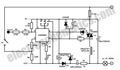
The light dimmer control circuit utilizes active timing capacitor reset and AC line zero-crossing synchronization to enhance performance and reliability. The inclusion of 13 low-cost components ensures affordability while maintaining effective functionality. The design's ability to provide smooth dimming performance without the snap-on effect is a significant improvement over traditional TRIAC dimmers, which are often plagued by abrupt transitions in light intensity.
In practical applications, this dimmer can be effectively used for both lighting and fan speed control. The mention of utilizing a standard light bulb dimmer for a 220V fan demonstrates its versatility. The cascading feature of the Arduino dimmer project allows for multiple lamps to be controlled sequentially, providing a sophisticated solution for lighting management in larger spaces.
The 555 timer configured as an astable multivibrator serves as the core of the dimming mechanism, generating pulse-width modulation (PWM) signals that control the VMOS transistors. These transistors are capable of handling significant power, up to 40 watts, making them suitable for a variety of lighting applications. The use of PUTs in the trigger circuit further enhances the robustness of the design, allowing for reliable operation across different load conditions.
Overall, this light dimmer control circuit represents an innovative approach to dimming technology, combining affordability, ease of use, and advanced features to meet modern lighting needs.This light dimmer control has active timing capacitor reset or AC line zero-crossing synchronization. The 13 additional components are garden variety and cost less than $2. Performance at the low end is exceptionally smooth and snap-free better even than the TRIAC Dimmer Avoids Snap-ON version that uses a passive reset.
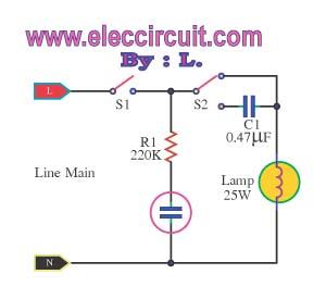
We are all familiar with the snap-on phenomenon of inexpensive TRIAC dimmers that are often used to control incandescent lamps turn the pot until the light comes (snaps) on and then reduce the setting to make it dimmer but don`t turn it too low because the light extinguishes and then the process must be repeated. However, . Hi guys, just a short article about a light dimmer switch that I opened a few days ago. I wanted a way to adjust the speed of a 220V fan and a friend of mine told me that I can use a regular and cheap light bulb dimmer for this.
I told him it might not work but he was so sure about it so I had to test it and of course it. This Arduino lights dimmer project is based on Doug Hitchcock`s comment: I need to have a lamp dimmer that can cascade from one lamp to the next (up to 4 lamps). Basically, when you close a switch, the first lamp begins to light from dim to 100%. Once lamp #1 reaches 100%, then that triggers dimmer circuit #2. This light dimmer is used to dim the intensity of 12V light bulbs using the well-known 555 timer that is configured as an astable multivibrator.
The pulses from pin 3 are used to control the VMOS transistor BUZ20, BUZ72 or 10N10. The maximum dissipated power must not exceed 40 watts. You may use the transistor without a. This SCR phase control works much like the common TRIAC dimmer, but has numerous advantages including increased current capability, robustness and absence of minimum voltage snap-on. A complementary, symmetrical trigger circuit consisting of two PUTs (programmable unijunction transistors) enables firing of two anti-parallel.
🔗 External reference
Related Circuits

Infrared light reflected off a finger is used to activate this switch circuit. Drawing only 30 µA from a 3 V supply, this circuit will detect a human finger with a range of about 1 inch. The sensor uses...
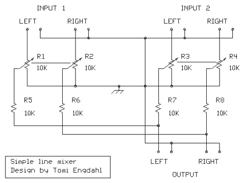
The mixer circuit described features three line inputs and three microphone inputs. The microphone inputs are designed for low impedance dynamic microphones with a range of 200 to 1000 ohms. Alternatively, an electret condenser microphone (ECM) can be used,...
An efficient automatic solar garden lights circuit with minimal components. The notable feature is that it operates entirely automatically, with the solar panel functioning as a light detector. The automatic solar garden lights circuit is designed to provide illumination in...
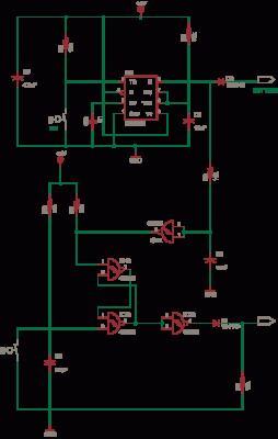
This circuit is a simple -5V power supply using a 555 timer, designed for low-power analog applications involving FET operational amplifiers. The circuit converts +5V to -5V to create a dual power supply. It operates as a 555 astable...
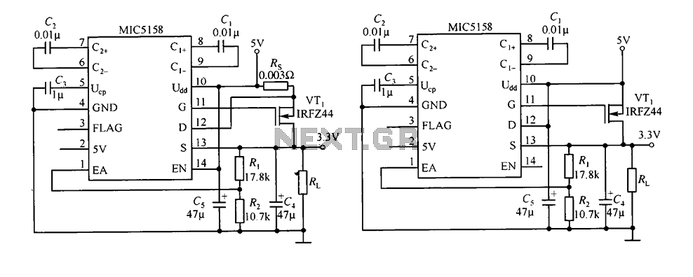
The circuit consists of peripheral components for the MIC5158, a linear regulator that converts a 5V input into a 3.3V output with a maximum current of 10A. When the input voltage (Ui) is 5V, an N-channel MOSFET, specifically the...
This is an automatic light dimmer circuit that eliminates the need for manual adjustment of light levels. It utilizes a Light Dependent Resistor (LDR) to detect ambient light conditions, which in turn controls a Triac to adjust the brightness...
Warning: include(partials/cookie-banner.php): Failed to open stream: Permission denied in /var/www/html/nextgr/view-circuit.php on line 713
Warning: include(): Failed opening 'partials/cookie-banner.php' for inclusion (include_path='.:/usr/share/php') in /var/www/html/nextgr/view-circuit.php on line 713