
Light following robot
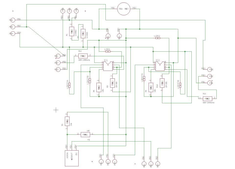
In this circuit setup, the primary concerns revolve around motor control and power management. The motors are exhibiting erratic behavior likely due to insufficient power supply isolation and grounding issues. The PICAXE microcontroller, which controls the motors, requires a stable power supply to function correctly. When motors are powered from the same source, voltage dips during motor operation can lead to microcontroller resets, causing the erratic behavior observed.
To enhance the reliability of the system, it is critical to implement proper decoupling techniques. This involves placing decoupling capacitors close to the power pins of the PICAXE to filter out high-frequency noise and stabilize the power supply. Ceramic capacitors (typically 0.1µF) are recommended for high-frequency filtering, while larger electrolytic capacitors (e.g., 100µF) can help manage low-frequency fluctuations caused by motor startup or load changes.
The grounding scheme must also be addressed. A star grounding configuration is advisable, where all grounds converge at a single point to minimize ground loops and voltage differentials. This arrangement helps ensure that return currents from the motors do not interfere with the PICAXE's ground reference.
The use of separate battery packs for the motors and the PICAXE is highly recommended. This approach not only isolates the power supplies but also allows for the selection of batteries that can handle the current demands of the motors without affecting the microcontroller's operation. When connecting the grounds of the two supplies, it is essential to do so at a point that is as close to the power source of the motors as possible.
In conclusion, addressing the power supply and grounding issues will significantly improve the performance of the motors and the overall stability of the circuit. Implementing these changes will help mitigate the erratic behavior and ensure reliable operation of both the motors and the PICAXE microcontroller.One of the motors always seem to hesitate and be on or off randomly. Also the motors are just very unpredictable in general (with this setup that is). When I use them independently they work fine without any hesitation or anything. Regarding your GPS unit, it does have a Low Voltage TTL serial output on the connector. I can`t find a decent datasheet to look at so do not know the voltage range for this output (3V at a guess). Not sure what your issue is with the servo`s. My guess is that you need to ensure the earths/0V are good and that there is good decoupling caps around the 08M. I`d agree with the comments above (#4) where the supply has not been seperated for the servo and picaxe.
The servo start-up, running or change in direction could cause a dip in power to the picaxe. you`ll see erratic movement but the picaxe is seeing brown out and power on resets. The more "worn" the batteries become the more common the problem. Use of an LED indication may help with diagnosis, say turn on an LED for 1/2 second. Turn off and start the servo, if you`re seeing the LED come on again then you`re seeing the program restart after some sort of reset! The easy solution is seperate battery packs and a common 0v. The location of the common point can be important, you don`t want return current from the motor passing the picaxe (it can raise the potential of the "0V" to picaxe), give it a short route back to it`s battery.
Running the servo`s from another supply is not accepteable in the end but to get it working atleast, it is. I tried using a dedicated supply for the servo`s with the GND connected to GND on the supply powering the circuit but the same problem perists.
I have capacitors over the picaxe`s (no idea if they are ceramic or not but you can see them on the pictures) and a 100uF capacitor over the power supply. 🔗 External reference
Related Circuits

This circuit is used to trigger a camera's electronic shutter circuit when a flash of lightning is present. This circuit would also work for photographing fireworks displays or other events involving flashes of light. More: In a nutshell, the...

This light meter features an eight-decade range. Bias current compensation enables an input current resolution of better than ±2 pA over a temperature range of 15 °C to 55 °C. The light meter is designed to measure luminous intensity across...

A reed switch is utilized in a TV highlights cancellation circuit. A brightness potentiometer is grounded in series with the reed switch. Under normal operation, the reed contact remains closed, allowing the capacitor C to charge to approximately 160V....

All files are found using legitimate search engine techniques. This site does not condone hacking into sites to create the links it lists. It is assumed that all links found on the search engines used are obtained legally and...
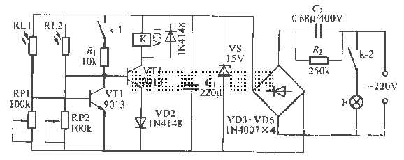
This is a remote-controlled light switch circuit that can be used for remote control toys, flashlight operation, or laser pointers. When the light from a torch illuminates the photosensitive resistor RL2, its resistance decreases, causing transistor VT2 to turn...

Currently, nearly all computer systems include logic blocks designed for interfacing with a USB port. In practical terms, a USB port can provide more than 100 mA of continuous electric current at 5V to the peripherals connected to the...
Warning: include(partials/cookie-banner.php): Failed to open stream: Permission denied in /var/www/html/nextgr/view-circuit.php on line 713
Warning: include(): Failed opening 'partials/cookie-banner.php' for inclusion (include_path='.:/usr/share/php') in /var/www/html/nextgr/view-circuit.php on line 713