
light gate with counter
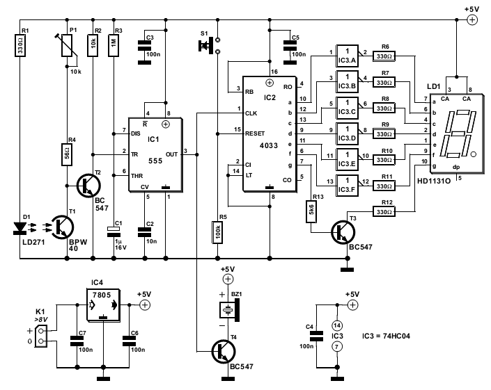
The circuit operates by utilizing infrared light to create a counting mechanism based on interruptions of the beam. The IR diode (D1) continuously emits infrared light, which is directed toward the IR transistor (T1). When the path of this light is unobstructed, T1 remains in a conductive state, keeping the voltage at its collector low enough to prevent T2 from turning on.
When an object interrupts the infrared beam, T1 receives less light, reducing its conduction and causing the collector voltage to rise. This change triggers T2, which sends a negative pulse to IC1. The monostable multivibrator within IC1 generates a high output for one second, allowing the buzzer to sound and providing a visual indication on the 7-segment display via IC2 and its decoder.
The output from IC1 not only provides an auditory alert but also serves as a clock pulse for IC2, which counts each interruption. The design incorporates a reset switch (S1) for convenience, allowing the user to clear the count when necessary.
For applications requiring different timing intervals, the circuit has been designed to allow easy adjustments to the timing components (R3 and C1), providing flexibility based on user requirements. The construction of the circuit should focus on optimizing the light path and minimizing interference from ambient light to enhance the reliability and accuracy of the counting mechanism. The inclusion of a potentiometer (P1) adds an additional layer of customization, enabling the user to adjust sensitivity based on the specific environment in which the circuit is deployed.The circuit described here counts the number of times that an infrared beam is interrupted. It could be used to count the number of people entering a room, for instance, or how often a ball or another object passes through an opening (handy for playing shuffleboard). The heart of the circuit consists of you guessed it a light gate! Diode D1 is an IR diode that normally illuminates IR transistor T1. The light falling on T1 causes it to conduct to a certain extent. The resulting voltage on the collector of T1 should be just low enough to prevent the following transistor (T2) from conducting. This voltage can be adjusted within certain limits using P1. As soon as an object comes between D1 and T1, the light shining on T1 will be partially or fully blocked, causing the IR transistor to conduct less current.
As a result, the voltage on its collector will increase, producing a brief rise in the voltage on the base of T2. This will cause T2 to conduct and generate a negative edge at IC1. This negative edge will trigger the monostable multivibrator, which will then hold the output signal on pin 3 high` for a certain length of time (in this case, one second).
Atthis point, two things will occur. First, a buzzer will be energised by the output of IC1 and produce a tone for approximately one second. When the buzzer stops, a negative edge will be applied to the clock input of IC2, causing the counter in IC2 to be incremented by 1.
IC2 is conveniently equipped with an internal binary-to-BCD decoder, so its outputs only have to be buffered by IC3 and T3 to allow the state of the counter to be shown on the 7-segment display. Switch S1 can be used to reset the counter to zero. If a one-second interval does not suit your wishes, you can modify the values of R3 or C1 to adjust the time.
Increasing the value of R3 lengthens the interval, and decreasing it naturally shortens the interval. The same is true of C1. When building the circuit, make sure that T1 is well illuminated by the light from D1, while at the same time ensuring that T1 sees` as little ambient light as possible.
This can best be done by fitting T1 in a small tube that is precisely aimed toward D1. The longer the tube, the less ambient light will reach T1. The sensitivity of the circuit can be adjusted using P1. 🔗 External reference
Related Circuits
The 15V DC supply is derived from a nominal 230/24V center-tapped AC transformer (T1) and a full-wave rectifier (D5 & D6). A Zener diode (D4) is included to limit the DC voltage to a maximum of 15V. Triacs (D7,...
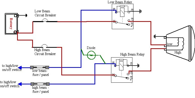
There is a need for improved headlights. Research has been conducted, including participation in ongoing forum discussions; however, basic information is still required. To enhance the performance of vehicle headlights, several factors must be considered, including the type of bulbs...
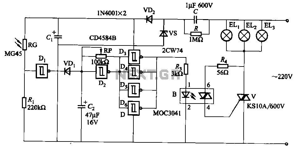
The circuit utilizes a CD4584B six Schmitt trigger integrated circuit (IC) with components Di and Ri forming a photometric circuit. D2, along with RP and C2, comprises an adjustable frequency ultra-low frequency oscillation device, where RP serves as an...
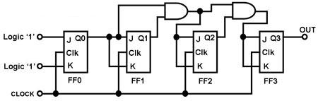
The circuit in Figure 1 is a 4-bit asynchronous counter, also known as a ripple counter. It consists of four J-K flip-flops with their J and K inputs connected to logic 1. This configuration causes the output of each...

The circuit for the Digital Tachometer/RPM Counter consists of a few components. They should be connected according to the provided circuit diagram. The PIC used is on a demonstration board, meaning the clock, power, and ground pins are already...
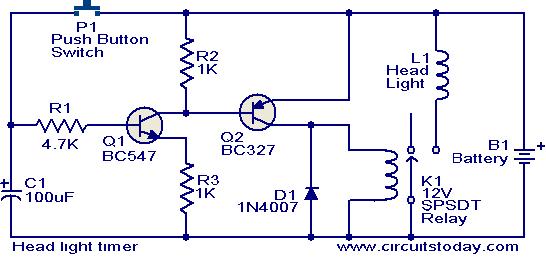
This circuit is a compact timer that keeps the headlights of a car on for approximately 1.5 minutes before turning them off. Incorporating this circuit into a vehicle allows access to dark areas without the need to return and...