
Low-cost-frequency-counter

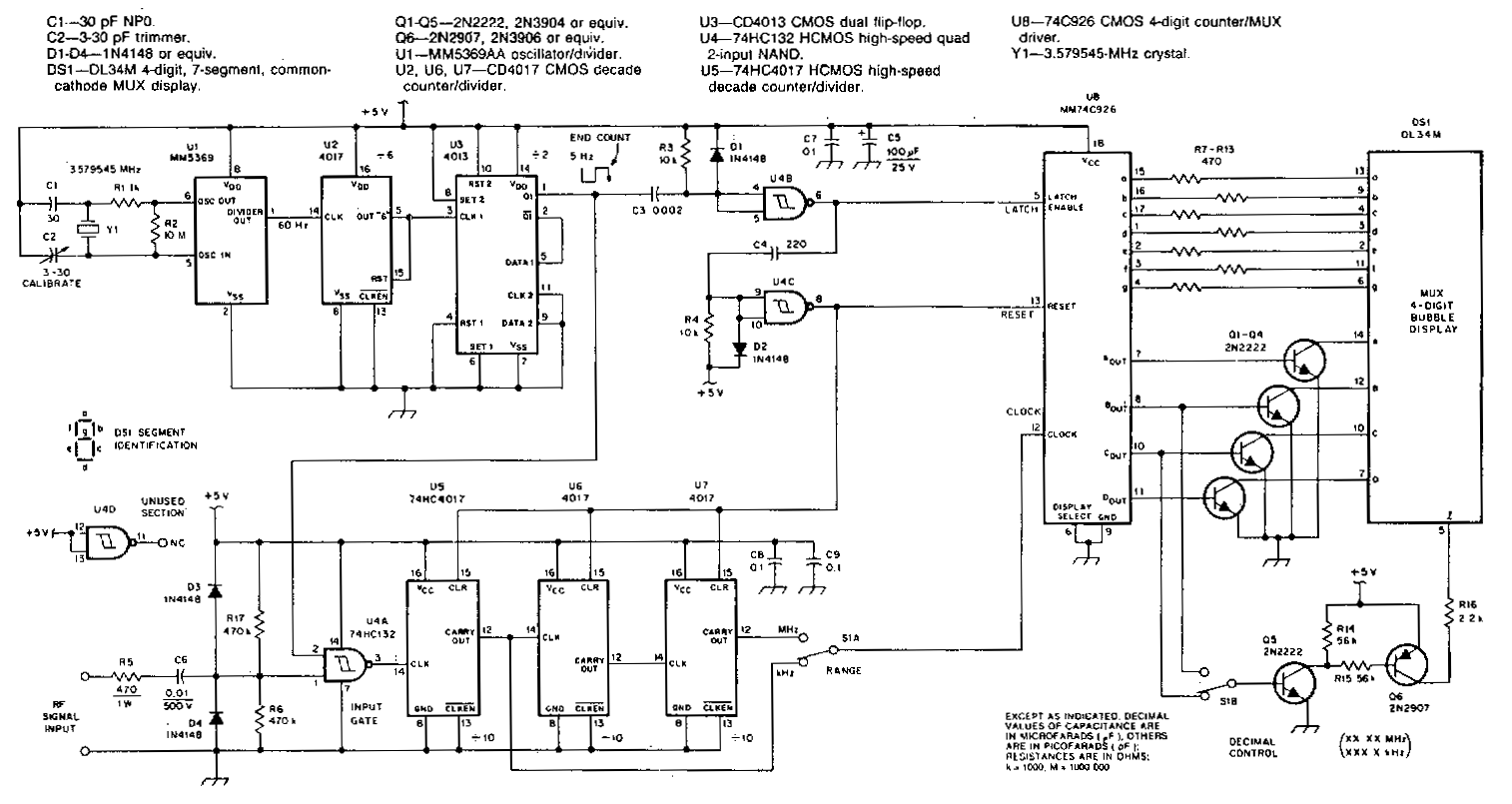
This counter utilizes a four-digit display, which can show frequencies ranging from 1 to 40 MHz when the range switch is activated, achieving a resolution of 100 Hz. The MM74C926 CMOS integrated circuit features a four-digit decimal counter that can latch a specific count and subsequently drive a seven-segment, common-cathode multiplexed (MUX) display. The operation of the counter is illustrated in the block diagram and schematic. A crystal-controlled timer, comprising U1 through U3, generates a 5 Hz square wave for timing the frequency count. Y1 is a TV color-burst crystal that operates within a stable circuit to regulate the oscillator frequency.
U1 functions as the oscillator and divides the fundamental operating frequency of 3.579545 MHz to yield a square-wave output of 60 Hz. U2 further divides the 60 Hz output from U1 by six, resulting in a 10 Hz output, which is subsequently divided by two in U3, a dual flip-flop, to generate the 5 Hz pulse. A quad, two-input, Schmitt-triggered NAND gate U4 is employed for gating the RF signal input and producing counter control pulses, with section U4D remaining unused. The 5 Hz output pulse from U3 is fed into the RF signal input gate at pin 2 of U4A. When the timer output signal is low, the gate remains closed.
The circuit operates by leveraging the MM74C926's capabilities to count and display frequencies accurately. The crystal-controlled timer ensures precise timing, which is critical for frequency measurement applications. The oscillator (U1) sets a stable frequency that is divided down to generate the necessary timing pulses. U2 and U3 serve as frequency dividers, enabling the generation of the 5 Hz pulse essential for counting operations.
The use of a Schmitt-triggered NAND gate (U4) enhances the reliability of the signal gating process, ensuring that only valid RF signals are counted, which minimizes errors during frequency measurement. The integration of a common-cathode multiplexed display allows for the visualization of the counted frequency in a user-friendly manner. This design is particularly suitable for applications requiring precise frequency measurement and display, such as in communication systems and signal processing equipment. The overall architecture ensures that the counter is both efficient and accurate, making it a valuable tool in electronic measurement systems.This counter uses a four-digit display, but with a flip of the range switch, it can display frequencies from 1 to 40 MHz, with a resolution of 100Hz. The MM74C926 CMOS IC contains a four-digit decimal counter that can latch a given count and then use this information to drive a 7 -segment, common-cathode multiplexed (MUX) display.
The block diagram and schematic show the operation of the counter. Crystal-controlled timer U1 through U3 produces a 5-Hz square wave used for timing the frequency count. Yl is a TV color-burst crystal operating in a reliable circuit that controls the oscillator frequency.
U1 acts as the oscillator and also divides the fundamental operating frequency of 3.579545 MHz to produce a square-wave output of 60Hz. U2 divides the 60-Hz output of U1 by six. In turn, the 10-Hz output of U2 is divided by two in U3, a dual flip-flop, to produce the 5-Hz pulse.
A quad, two-input, Schmitt-triggered NAND U4 is used for gating the rf-signal input and for generating the counter control pulses-Section U4D is unused. The 5-Hz output pulse of U3 is applied to the rf-signal input gate at U4A pin 2. When the timer output signal is low, the gate is closed.
Related Circuits
This counter features a four-digit display that can be switched to display frequencies ranging from 1 to 40 MHz, with a resolution of 100 Hz. The MM74C926 CMOS IC serves as the four-digit decimal counter, which can latch a...