
Light Operated Relay Circuit

The circuit utilizes a light-dependent resistor (LDR) as its primary sensing element. The LDR exhibits a decrease in resistance when exposed to light, allowing it to function effectively in detecting ambient light levels. When the light level drops below a predetermined threshold, the resistance of the LDR increases, triggering the operation of a transistor or operational amplifier configured as a comparator, which subsequently activates the relay.
The relay serves as an interface between the low-power control circuit and the high-power AC load, ensuring safe operation. When the relay is energized, it closes its contacts, allowing current to flow to the connected lamps or other AC devices. The circuit may also include a potentiometer to adjust the sensitivity of the LDR, enabling customization based on the specific ambient light conditions of the installation environment.
Additional components may include a diode across the relay coil to prevent back EMF from damaging the control circuit when the relay is de-energized, as well as capacitors for filtering and stabilization purposes. The power supply for the circuit can be derived from a low-voltage source, ensuring that the control side remains isolated from the high-voltage AC side for safety.
This circuit is particularly beneficial in applications where manual switching is inconvenient, providing automatic operation based on environmental light conditions, thus enhancing energy efficiency and user convenience.This light sensitive circuit can operate a relay to switch on lamps or any AC loads when it senses darkness. It is ideal to use as switch less night lamps.. 🔗 External reference
Related Circuits
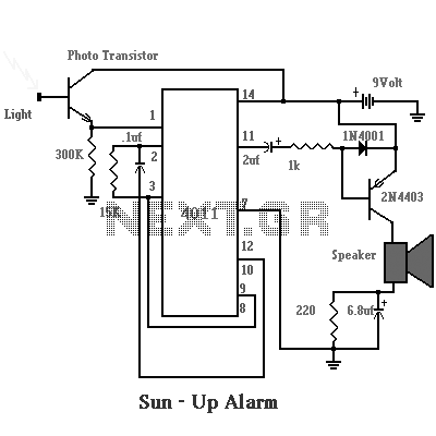
This is a simple photo-sensing circuit. When light hits the photo-transistor, it triggers the 4011, which drives a loudspeaker. It is easy to make and can be very useful as well. The described photo-sensing circuit utilizes a photo-transistor as the...
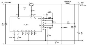
The circuit illustrates a TL494 pulse width modulated step-down converter schematic. This circuit allows for testing of line regulation, load regulation, output ripple, short circuit current, and efficiency under various input voltage conditions. A detailed table of these tests...
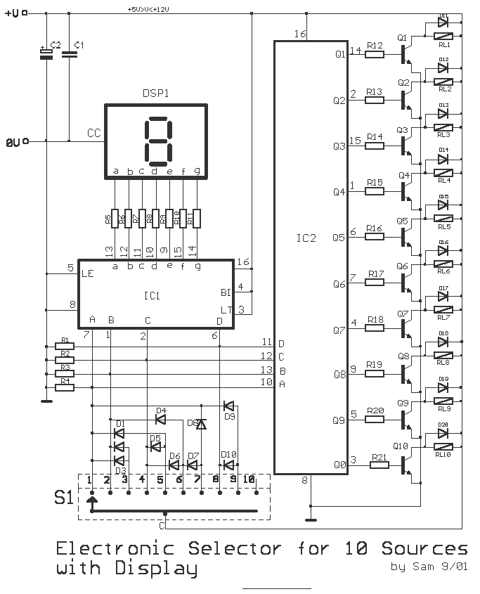
This is a circuit for alternative sources selection. It combines mechanical selection using a rotating switch S1, the electronic drive of the relays RL 1-10 and also the optical indication of the selection by the Display DSP1. The function...
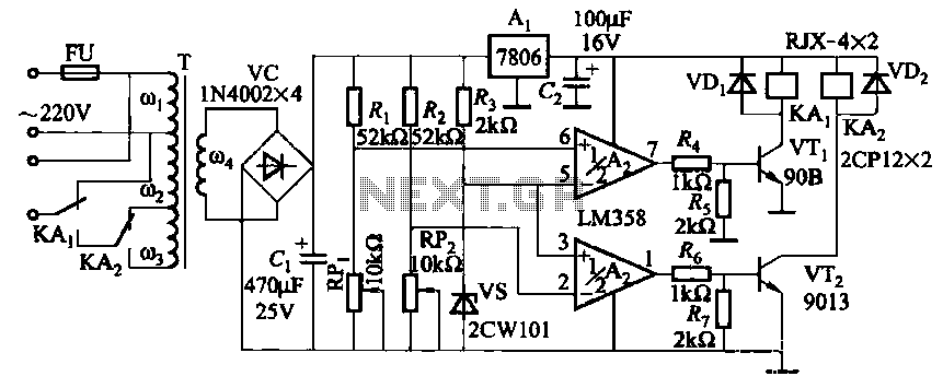
It utilizes two LM358 operational amplifiers, A2 and Ar, to create a voltage measurement comparison control circuit for upper and lower limit voltage settings. The circuit includes a Raspberry Pi adjustment potentiometer (RPi) and an additional potentiometer (RP2) to...
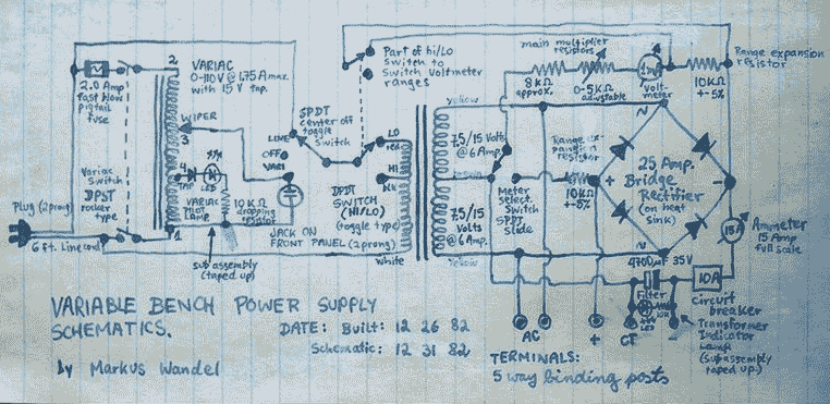
This power supply is able to deliver adjustable center-tapped DC from 0 to about 30 volts, as well as AC directly from the Variac and from the main transformer before the rectifier. What's primitive by today's standard is that...

This is a simple touch switch circuit where the 555 timer is configured as a one-shot multivibrator triggered by touching the touch terminal. In monostable mode, the timer generates a fixed pulse of approximately 4 seconds whenever the trigger...