
light sensor

The described circuit operates effectively in applications where light detection is essential, such as in automated lighting systems or security alarms. The voltage divider configuration with the LDR allows for the detection of varying light levels, translating these variations into digital signals through the NPN transistor inverter. The choice of a 5-volt regulator is advantageous for compatibility with various microcontrollers and digital logic circuits, ensuring that the output remains stable under different load conditions.
In the schematic design process using Eagle, the systematic addition of components facilitates the organization of the circuit layout. The use of symbols for GND and VCC streamlines the design, making it easier for engineers to visualize connections and maintain clarity. The decoupling capacitors play a critical role in maintaining signal integrity by smoothing out voltage fluctuations and preventing unwanted noise from affecting the performance of the circuit.
Overall, the integration of these components and their configuration not only enhances the functionality of the light detection circuit but also ensures that the design process is efficient and manageable, ultimately leading to a reliable and effective electronic solution.When we hook up this element in a voltage divider configuration, we can make a high and low signal based upon how much light hits the sensor. This is further filtered by using an NPN transistor in an inverter configuration to generate a purely digital signal.
This circuit allows you to produce a 1 or a 0 that correlates to whether the sensor is su bjected to light or is in shadow. The amount of light that triggers the sensor is based on resistor R. (the resistor hooked up in the voltage divider with the LDR) Eagle is a very powerful tool and can make designing complicated circuits a breeze. Its much easier to draw a circuit out on eagle than to fumble around with a breadboard guessing and checking along the way.
This is what comes up once you create a new schematic. Your first job is to start adding devices to your circuit. This is done by pressing the add devices button. You can begin typing what part you need, first thing we`re going to do is assemble the power supply so we have a steady potential across our circuit. We want a positive voltage regulator in a TO-220 package. A TO-220 package is fairly common package as its cheap and very easy to work with and we don`t have to worry about overheating too much because the package can handle a lot of heat.
Most of the time as well the package has a mounting hole for a heat sink a swell. Once we select the part we want we can add it to our circuit. For the power supply were going to need two capacitors and a voltage regulator as well as inputs for our voltage from our source. Once we place all the parts we have to hook everything up. For this, we use the wire hookup tool. We link all the parts like we normally would in a circuit with wire. We have to take one more step however, we have to use the node tool at any junction where two devices connect.
Just because a wire and a device touch, doesn`t mean they`re linked. We must use the node tool to link the devices and make a connection. This is very important as unlinked nodes will produce an improper PCB design when we eventually get to that stage. One thing you`ll notice is the GND and VCC "devices. " These are symbols we use to note common points in the circuit. We use a GND symbol to denote the ground. Therefore, any point in the circuit that connects the ground, connects to this symbol. This way of designing our schematic makes things look cleaner and allows us to separate functioning parts of our circuit into blocks that can be modified separately.
The power supply provides us with a known potential. When building this circuit we are going to use a 5 volt positive voltage regulator, which on the output gives us a steady 5 volts irregardless of the input voltage (assuming its DC and within specs). The two capacitors act as filters, filtering out noise that might be introduced on our line. The capacitors in that configuration are called decoupling/bypass capacitors and are a type of low pass filter.
🔗 External reference
Related Circuits
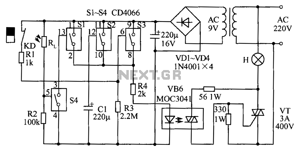
The circuit diagram illustrates a group of four analog electronic circuit switches (S1 to S4). Switches S1, S2, and S3 are utilized in a parallel delay circuit. When the power is activated, resistor R4 drives the triac VT, which...
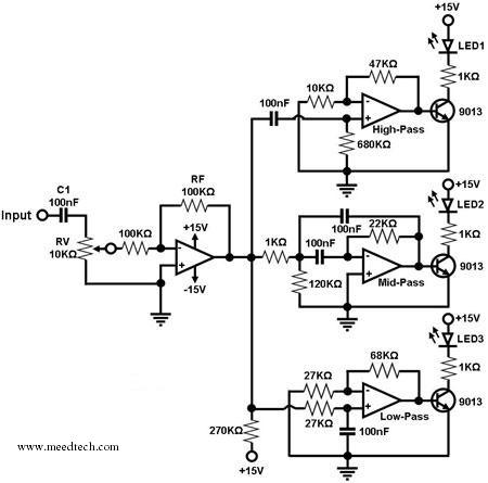
A simple circuit for converting an audio signal (such as one that comes from the output terminals of a CD player). The circuit basically consists of a buffer/amplifier stage and three filter circuits: a high-pass filter, a mid-pass filter,...
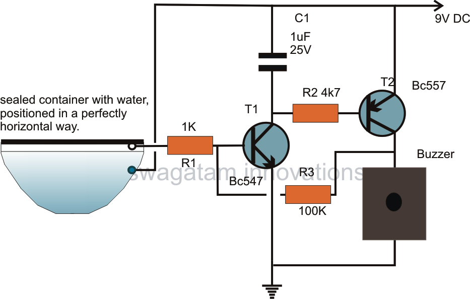
The article presents a circuit concept that features an innovative method for detecting minimal shocks caused by potential earthquake tremors. This circuit is highly sensitive, capable of detecting tremors of magnitude 4 on the Richter scale, while remaining unaffected...
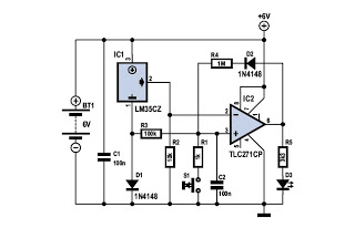
To determine whether it is freezing, it is necessary to measure the temperature accurately using a reliable temperature sensor. The LM35CZ, which operates between -40 to 110 °C, has been chosen for this purpose. This sensor generates an output...
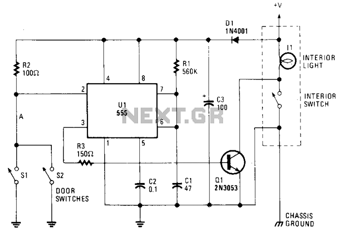
The circuit maintains the courtesy light's illumination for 30 seconds after the door is closed. The lead from the door switch is disconnected and linked to the 555 timer circuit. The 555 timer is configured in monostable mode and...
This circuit is relatively simple yet valuable, as it offers a high-quality interior light delay feature. The circuit for the interior light delay is designed to control the duration for which the interior lights remain illuminated after a door is...
Warning: include(partials/cookie-banner.php): Failed to open stream: Permission denied in /var/www/html/nextgr/view-circuit.php on line 713
Warning: include(): Failed opening 'partials/cookie-banner.php' for inclusion (include_path='.:/usr/share/php') in /var/www/html/nextgr/view-circuit.php on line 713