
Light turning bike using IC LM3909
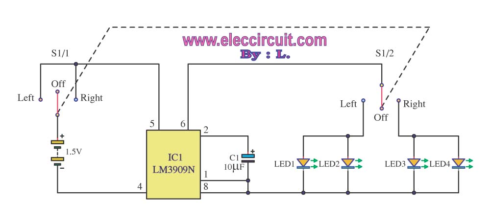
The bicycle turning light circuit enhances visibility and safety for cyclists during turns. It utilizes a simple yet effective design that incorporates a power supply of 1.5V to activate a timer IC (IC1), which serves as the oscillator. The switch (S1) acts as the user interface, allowing the cyclist to indicate the desired direction of the turn.
In normal operation, the switch remains in the OFF position, ensuring that no power is consumed unnecessarily. When the cyclist intends to turn right, the switch is toggled to the right position, activating the circuit. The oscillator within IC1 generates a square wave signal, which is output at pin 6. This output controls a dual switch (S1/2), enabling the simultaneous flashing of LEDs 3 and 4, thereby signaling to following vehicles the intent to turn.
Conversely, when the switch is moved to the left position, the oscillator's output changes, triggering LEDs 1 and 2 to blink. The frequency of the blinking is adjustable based on the capacitance of capacitor C1, allowing for customization of the visual signal's speed according to user preference or visibility requirements.
This circuit is particularly advantageous for its simplicity and low power consumption, making it suitable for battery-operated bicycles. The design can be further enhanced by incorporating additional features such as a low-voltage cutoff to protect the battery or using more energy-efficient LED technology to extend the operational time between battery replacements. Overall, this bicycle turning light circuit represents a practical solution for improving cyclist safety on the road.Usual already a bicycle has will no Light turning. If want to turn a car may be born dangerous can go up. Because of a car that drive to follow come to don`t know that turn thus. We should enhance the safety gives with one self with building light turning bike circuit this upward. The work of the circuit be in usual time switch S1 will stay in a p osition OFF. If the circuit will turn to the right move switch S1 go to a position Right have power supply 1. 5V, go to at IC1 which be IC1 work oscillator generator come out pin 6 ways change contact switch S1/2 make LED3, LED4 will flasher at the same time conversely. If turn to the left move switch S1 go to at a position Left frequency signal that pin 6 s of IC1 change contact switch S1/2 make LED1, LED2 blink at the same time.
By the speed in something flasher depend on the value of C1 this circuit can work long ago. Because the circuit will work especial when open light turning only. 🔗 External reference
Related Circuits
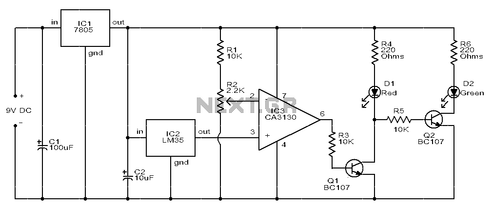
The circuit consists of two light-emitting diodes (D1 and D2) whose operation is controlled by the ambient temperature. A temperature sensor, the LM35, generates an output of 10 mV for each degree of temperature increase. A reference potentiometer, R2,...
This LED flasher circuit is a classic two-transistor flip-flop. It is a popular circuit often built by beginners in electronic circuit design. The schematic diagram of this well-known LED flasher circuit consists of two transistors, two capacitors, four resistors,...
When a vehicle is driven on the highway at night, it is essential that the light beam is of high intensity and illuminates the road at a sufficient distance. To achieve optimal visibility during nighttime driving, especially on highways, the...
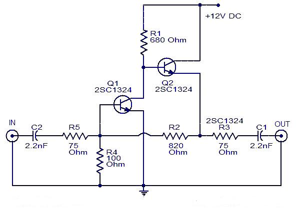
This is a cable TV amplifier utilizing two transistors. The amplifier circuit is designed for cable TV systems using 75 Ohm coaxial cables and operates effectively up to 150 MHz. Transistor T1 is responsible for amplification, providing an expected...
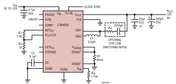
A very simple, high-efficiency switching mode buck-boost power supply circuit can be designed using the LTM4609 switching regulator IC. This circuit will provide a fixed output voltage of 12 volts. As illustrated in the schematic, the switching power supply...
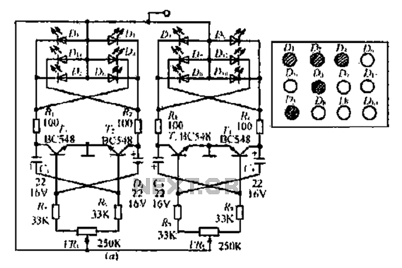
A circuit involving oscillations is composed of a Houle Wang oscillator that utilizes a transistor configuration with components labeled Ti, n, and n, along with a composition of Q constants for the cycle. The waveform can be modified by...
Warning: include(partials/cookie-banner.php): Failed to open stream: Permission denied in /var/www/html/nextgr/view-circuit.php on line 713
Warning: include(): Failed opening 'partials/cookie-banner.php' for inclusion (include_path='.:/usr/share/php') in /var/www/html/nextgr/view-circuit.php on line 713