
light up pumpkin

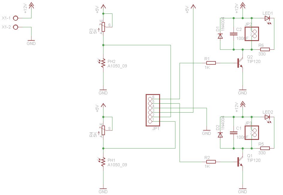
The circuit design consists of a basic LED driver configuration powered by a battery source, ensuring portability and ease of use. The photo sensor, typically a light-dependent resistor (LDR) or a phototransistor, is employed to detect ambient light levels. When the light levels fall below a predetermined threshold, the photo sensor triggers a transistor or a relay to complete the circuit, allowing current to flow through the LEDs.
To implement the adjustable lighting feature, a potentiometer is integrated into the circuit. This component enables users to fine-tune the sensitivity of the photo sensor, allowing for customization based on varying environmental lighting conditions. The LEDs, selected for their brightness and color, are connected in parallel to ensure uniform illumination.
For the physical assembly, the pumpkin should be prepared by carefully drilling holes to accommodate the LEDs while ensuring that the outer skin remains intact to conceal the lights during the day. This method enhances the aesthetic appeal of the project, making it an ideal decorative piece for Halloween or other events.
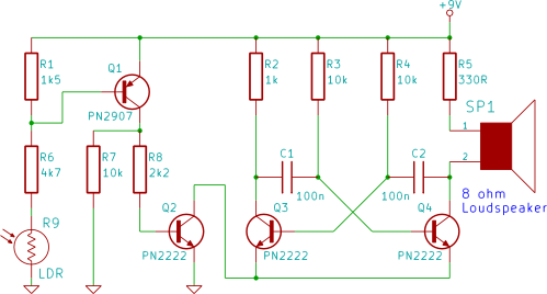
Safety is a significant consideration in this design, as it avoids the use of open flames or electrical cords, making it suitable for indoor and outdoor use. The project encourages creativity and experimentation, allowing individuals to modify the circuit or the enclosure as desired. The Evil Mad Scientist project website serves as a valuable resource, offering comprehensive guidance for assembling and troubleshooting the circuit, ensuring a successful and enjoyable experience for creators.The concept is that a pair of yellow LEDs are placed in an otherwise inconspicuous pumpkin, and a photo sensor allows the circuit to turn on the lights at night. The circuit itself is very straightforward, incorporating minimal components. There are two schematics listed on the project site, but we suggest using the one above with an adjustment pot so that you can adjust the lighting
for your given conditions. In the project, which definitely looks to be fun, they drill holes for the LEDs. Iwould suggest trying to drill a whole partially through the pumpkin, leaving a thin layer on the outer skin so that in the daytime there is no hint of the creepy effects thatcome outat night. Plus it is a safe effect to have on, no power cords or candles required. The Evil Mad Scientist project website includes step by step details, so we suggest going to have a look see if you are interested in creating such a project.
🔗 External reference
Related Circuits

This circuit is used to trigger a camera's electronic shutter circuit when a flash of lightning is present. This circuit would also work for photographing fireworks displays or other events involving flashes of light. More: In a nutshell, the...
This device is a simple timer, allowing to keep on the headlights of your vehicle for about 1min. and 30sec., e.g. when accessing some dark place, without the necessity of coming back to switch-off the lights. The circuit design for...
When sufficient light reaches the Light Dependent Resistor (LDR) in this circuit, an alarm tone is activated on the loudspeaker. This tutorial guides beginners in electronics through the step-by-step process of constructing the circuit on a breadboard. The circuit utilizes...
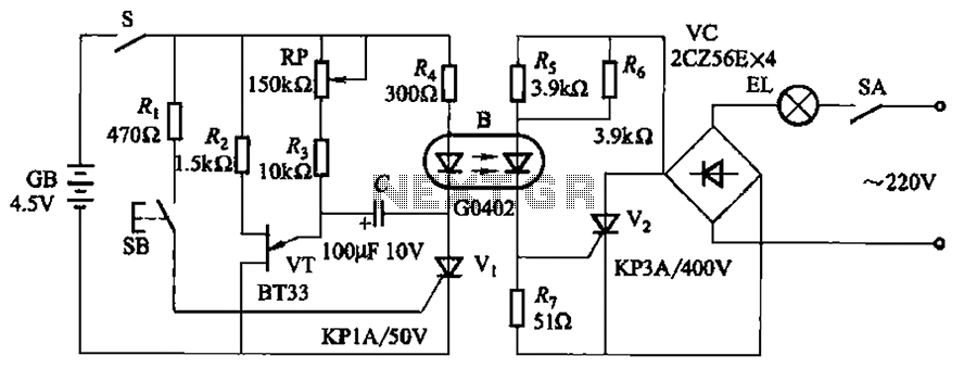
The circuit illustrated in Figure 2-48 consists of two configurations. Configuration 2-48 (a) operates using a 4.5V battery, while configuration 2-48 (b) employs AC capacitors to reduce the voltage supply. In configuration 2-48 (a), the delay time is influenced...
Dark Activated Switch or Porch Light Switch. This circuit activates a relay when the light level drops below a preset threshold. The light sensitivity can be adjusted using variable resistor VR1, and the relay contacts can control an external...
The figures above illustrate the fundamental concept of a robot, which comprises input and output devices connected to a central processing unit, often referred to as the brain. In this case, the Arduino acts as the brain, controlling all...