
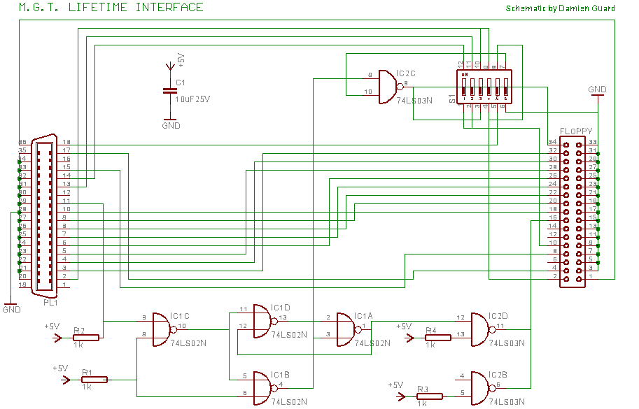
Lighting control circuit
The circuit design incorporates an operational amplifier (op-amp) configuration, specifically utilizing the LM387N for signal processing. The high-end shunt control mechanism is critical for regulating the output voltage to the shunt transistor, which is responsible for managing excess current and preventing overvoltage conditions. The shunt transistor operates in conjunction with a Darlington pair, allowing for efficient current amplification and control. The LED control circuit is designed to modulate the brightness of the LEDs based on the input voltage, employing a feedback loop to adjust the control voltage dynamically.
Incorporating a BuckPuck voltage regulator allows for efficient power management, ensuring that the LEDs receive the required voltage and current for optimal performance. The piecewise linear function implemented in the control circuit enables precise voltage regulation across varying input levels, facilitating a stable output even under fluctuating conditions.
The external shunt circuit is designed to accommodate multiple LED configurations, allowing for scalability in the lighting system. The Endor Star module's integration provides a robust solution for heat dissipation, essential for maintaining operational integrity in high-power applications. The PCB layout must be optimized for minimal parasitic inductance and capacitance, ensuring reliable performance in the face of mechanical vibrations typical in bicycle applications.
Overall, the design aims to deliver a cost-effective, efficient, and durable lighting solution for bicycles, leveraging modern electronic components and design techniques to overcome the limitations of existing products on the market.After being incredibly careful about every orientation of every weird transistor, I designed the board around a LM387N , which is not the chip I intended or the one that I had ordered ” LM258 (usually referred to as LM358, but the 258 works in the cold). I was testing the board before putt ing on the big components, and it was just not working, and in the end, it seemed like the op-amp was on drugs. In the end, I got out a magnifying glass to check the label. DOH! Up-update: After installing a pin-scrambler, it works roughly as predicted. The most important part of the circuit, the high-end shunt control, delivers 3. 85 volts to the base of the shunt transistor at 31. 1 volts. This is a perhaps a half-volt earlier than planned, but it`s a half-volt to the safe side. In the high 20s, the shunt is not activated, as planned. (1) the LED control sends a little more power to the lights than I had planned. Not lots, and it`s mostly a low-end effect. At 31. 1, the control voltage is 1. 7, which is exactly on target. At 22. 5 it is 2. 6 (plan, 3. 1) and at 12. 9 it is 3. 24 (plan, 3. 6) and at 9. 6 it is 3. 4 (plan, 3. 8). (2) the off-level shunt base voltage is 0. 6, where the plan was 0. 2. This should not be an issue with the particular Darlington shunt transistor; it claims to have a Vbe of 2.
8 volts. The new hub ( Shimano 3D71 ) produces too much power, at too high a voltage if your LED circuit does not use it all. The new plan uses a piecewise linear function of the input voltage to drive the voltage control circuit on a BuckPuck, plus a shunt to guard against overvoltage.
The idea is that at lower power, enough light is produced, but at high power, the excess is dumped into the lights, with the intent that somewhere between 30 and 31 volts, the LEDs are receiving near-maximum power (9-10 watts), and the shunt is activated to drain up to an amp (30 watts) to keep the voltage from going any higher. The shunt circuit allows an external device (as many as 7 LEDs!) to dissipate the power instead of the transistor.
My plan is to use an Endor Star (3 surface mount Luxeon Rebels on a single puck) that I bought but could not find a use for (could not heat sink effectively enough) to dissipate up to 10 watts externally. The goal is to ensure that the supply voltage is limited to 32 volts, no matter what, because the op-amp and the BuckPuck are rated for 32, the capacitors are rated for 35, and the diodes are rated for 40.
The combined circuit is just complex enough that it should be on a PCB, which should also make the result more durable. Vibration on a bicycle is a serious problem. CadSoft sells Eagle, software for designing printed circuit boards. The full version does way more than I need; the free version is enough for me, at least so far. The autorouter is mostly my friend, especially once I got used to its quirky habits. Quite a few zener diodes don`t reach their rated voltage until they have quite a few milliamps flowing through them.
If those milliamps are also flowing into the base of a transistor then the shunt will have a long, wasteful on ramp . Just because it looks like it works, how will it behave in the real world with slightly different parts Tinker with element values, tinker with resistor gain, try monkeying with the forward voltage on transistors.
Push things around till the simulation goes wonky, so that you can know how large your sensible-operation margins are. Oh yeah, about the copyright. I`d like to open source it, but cannot figure out how to put the whole GPL on one PCB. I`m a bit ticked off at all the bicycle lighting companies; everything costs too much, way too much. Bought retail, the cost of the components on this board is in the 15-20 dollar range, plus the buckpuck, which is another $15.
LEDs+lenses cost about $10 apiece, you need at least 3 for a bike (4 is better), unless you want 🔗 External reference
Related Circuits
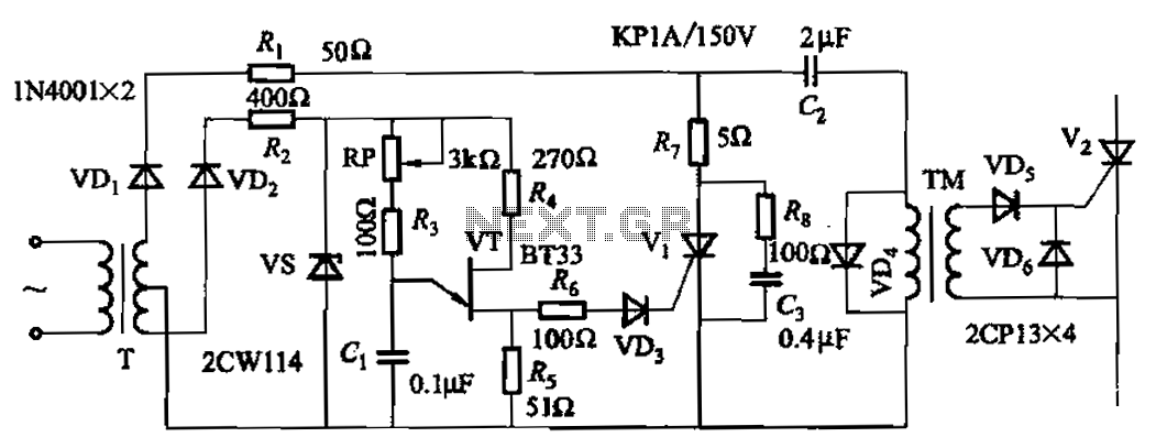
The adjustment potentiometer RP allows for modification of the pulse phase shift range, which spans from 0 to -1600, providing higher sensitivity. The circuit incorporating the adjustment potentiometer RP is designed to facilitate precise control over the phase shift of...
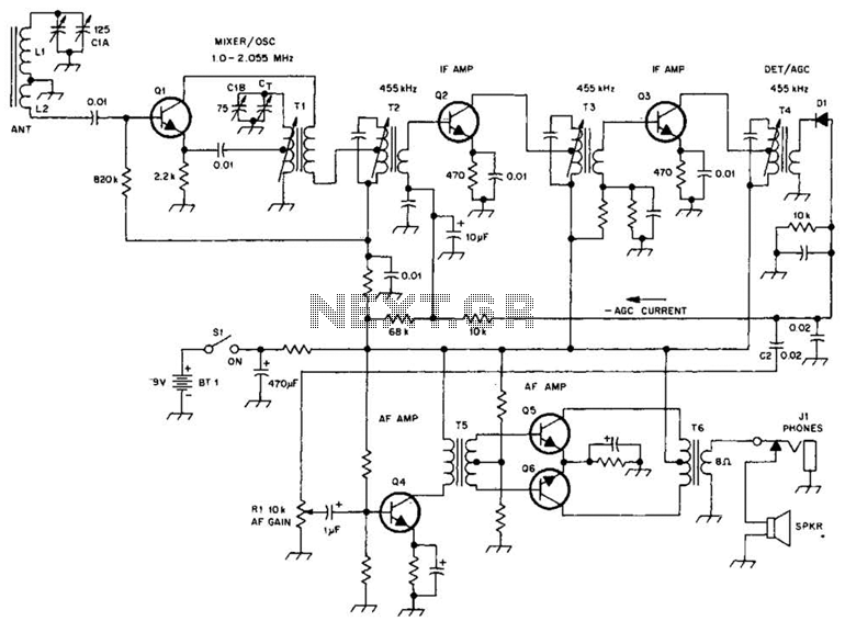
A schematic of a typical transistor AM radio is presented. This circuit utilizes npn transistors. It is a generic circuit; hence, specific values for some components are not provided. This circuit serves as a reference point for experimenters. The schematic...
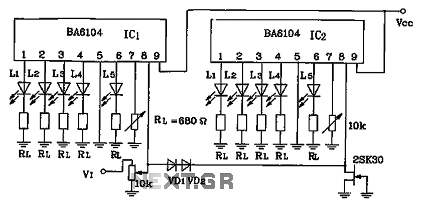
BA6104 is a five-digit LED level meter that functions as an LED display driver integrated circuit (IC). The configuration of the circuit is illustrated in the accompanying figure. The circuit utilizes a 10 by two-dot LED level display. The...
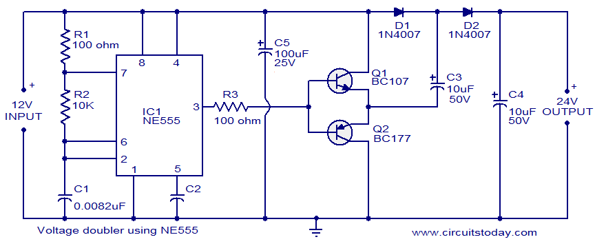
The circuit diagram of a simple voltage doubler using the NE555 timer is presented. In this configuration, the NE555 IC operates as an astable multivibrator at approximately 9 kHz. The bases of two transistors, Q1 and Q2, are connected...
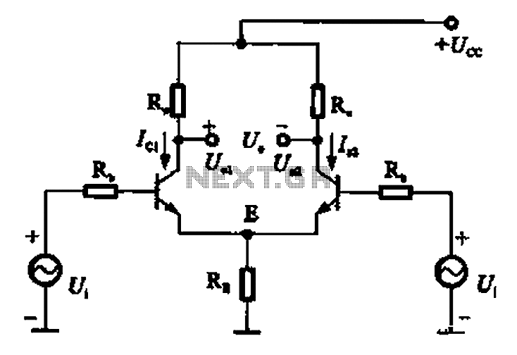
The common mode signal of an emitter-coupled differential amplifier circuit assumes that two equal small increases of the same polarity signal, referred to as the common mode signal, occur simultaneously. This results in an increase in the potential at...
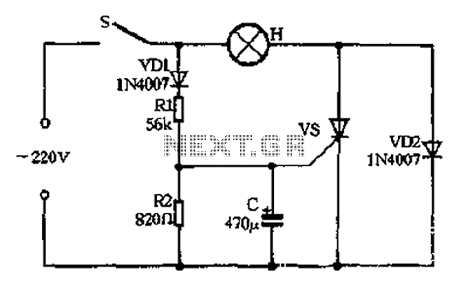
The circuit operates as follows: When the momentary switch S is activated, the voltage across the capacitor cannot change instantly, resulting in zero voltage across the SCR, which does not trigger. Consequently, the voltage cut-off occurs. In this scenario,...
Warning: include(partials/cookie-banner.php): Failed to open stream: Permission denied in /var/www/html/nextgr/view-circuit.php on line 713
Warning: include(): Failed opening 'partials/cookie-banner.php' for inclusion (include_path='.:/usr/share/php') in /var/www/html/nextgr/view-circuit.php on line 713