
Lightning Detectors
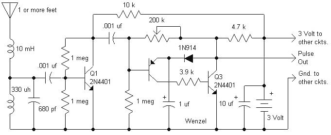
The lightning detector circuit operates primarily in the RF frequency range, specifically tuned to resonate at approximately 300 kHz, which is effective for detecting electromagnetic signals generated by lightning strikes. The telescopic antenna serves as the primary receiver, capturing these signals and transmitting them to the input of the RF section. The design emphasizes sensitivity and stability, utilizing a high-value resistor to manage the Q factor of the resonant tank formed by the antenna and inductors.
The amplification stage is critical, as it takes weak signals from the antenna and boosts them for further processing. The PNP-NPN transistor configuration creates a regenerative feedback loop that enhances the speed and reliability of the signal detection, ensuring that even brief pulses from distant lightning strikes can trigger the circuit effectively. The inclusion of a capacitor in the feedback loop allows for a quick reset, enabling the circuit to be ready for subsequent signals.
The overall design is modular, allowing for the integration of additional components such as lamps or meters. This flexibility enables users to customize the lightning detector according to their specific requirements. The use of standard components and a straightforward assembly approach makes this circuit accessible for hobbyists and professionals alike, promoting ease of construction and maintenance.The following circuit is an improved version of my original Lightning Detector designed to run on a 5 volt supply. The new circuit features a superior RF section with a single resonance near 300kHz and plenty of sensitivity.
The potentiometer was eliminated; simply adjusting the length of the telescopic antenna will give the desired sensitivity. T he circuit supply voltage was increased to 5 volts to allow the use of commonly available molded power supplies instead of batteries. Another not-so-obvious feature is that I have plenty of the inductors! (For inductors email charles@wenzel. com. ) The basic receiver is shown below. The antenna is a telescopic antenna that extends to two or three feet, the length is not critical. A high-value resistor (270k) is connected from the antenna to ground to control the Q and this value may be lowered if the circuit seems unstable but too low a value will destroy the sensitivity.
The 10 mH and 1 mH ( not uH) chokes are molded types but most moderately high-Q inductors will work fine and the rest of the parts are run-of-the-mill and not particularly critical. The transistors are all general-purpose types. Note: This circuit is intended to be used with one of the lamp options and any or all of the other options.
If no lamp is desired, add a 1 k resistor from the "pulses" output to 5 VDC. Below is an experimental version with an additional diode across the 82k. The diode helps the flasher to trigger on smaller pulses. the 82k may be 100k, if desired. The antenna, 10 pF capacitor, and the two inductors form a resonant tank at about 300 kHz, a good frequency for receiving energy from lightning. The two series inductors act as a matching network, feeding Q1 with a lower impedance version of the signal received by the antenna.
The 270k resistor lowers the Q of the resonant tank to prevent oscillation. Q1 amplifies the 300 kHz bursts and applies the larger signal to the base of a PNP transistor that forms a monostable "flasher" circuit with the last NPN transistor. When the RF signal pulls the PNP base voltage below the voltage on the 10 uF capacitor (plus about 0.
6 volts) the PNP turns on, turning on the NPN. Since the NPN is connected to the base of the PNP through the 82 k resistor, the PNP turns on even harder. This regenerative action causes the circuit to turn on quickly and fully, pulling the "pulses" line to nearly zero volts.
The circuit stays on until the 10 uF capacitor discharges at which point a similar reverse regenerative action causes the circuit to quickly switch off. The capacitor then quickly charges through the 1k resistor (in one of the lamp circuit options) and the diode and is ready for another pulse.
The prototype is built into a phenolic box using point-to-point wiring. The power switch is a single pole, double throw type with a center-off position. The power supply is connected to the center terminal and the speaker is connected to one of the outer terminals. Both of the outer terminals are also connected to the other circuitry through a couple of silicon diodes, one from each terminal.
One diode keeps the speaker from getting power in the `speaker off` position and the other diode is simply there so that the circuitry sees the same voltage in both `on` positions. Alternately, a switch could be added in series with the speaker to turn it off. After one storm, you will add the switch if you don`t include it at first! The diodes can be seen in the close-up of the power switch. Alternately, a ordinary single pole, single throw switch could be used with another switch in series with the brown wire to disconnect the speaker when the constant crackle becomes too annoying!
The basic circuit above is combined with any of the following circuits to complete the lightning detector. The prototype used the 5 volt lamp driver, meter circuit, and speaker circuit. Choose any or all of the above circuits and connect them across 🔗 External reference
Related Circuits
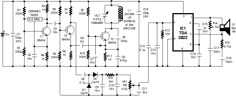
The circuit presented is a metal detector that operates based on the superheterodyne principle, which is commonly utilized in superhet receivers. It employs two RF oscillators, both fixed at a frequency of 5.5 MHz. The first RF oscillator consists...
This circuit is designed for liquid level or proximity detection. It operates by measuring the distance to a target through the reflection of an infrared beam. The device can detect the level of liquid in a tank without any...
Motion detectors commonly utilize ultrasonic sensors due to their sensitivity and rapid response. However, a significant drawback of these sensors is their tendency to react to environmental vibrations, such as sounds from passing cars or planes, leading to unexpected...
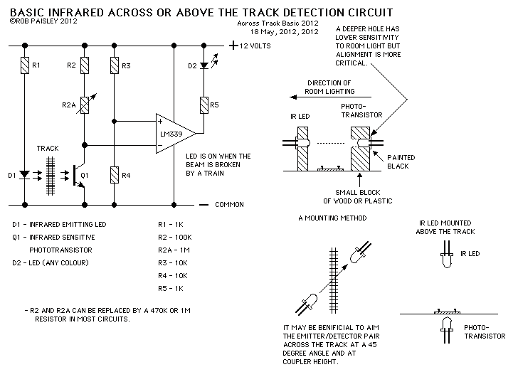
This page presents information on infrared - Across The Track train detection circuits. The circuits are designed around the LM339 comparator chip and can use a wide assortment of matched infrared - emitter / detector pairs. The basic circuit...
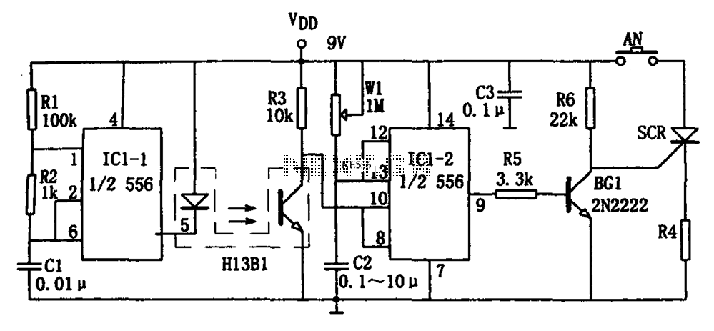
The circuit shown is a photoelectron pulse missing detection circuit. It includes an optoelectronic slotted switch H13B1, a dual time base circuit using a 556 timer IC, and several RC components that form a one-shot multivibrator. The design incorporates...

These circuits are utilized for the detection of single-sideband (SSB) and continuous wave (CW) signals. The beat frequency oscillator (BFO) injection is generally in the range of 0.5 to 1 V rms for both circuits. The operational frequencies can...