
Line-activated-solid-state-switch
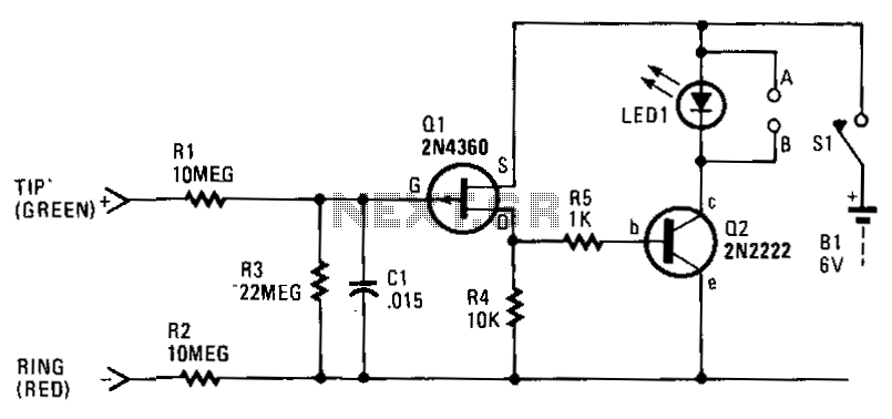
Each time a phone on the same line or calling number is taken off-hook, the circuit activates to control an external electronic circuit. If multiple extension telephones are connected to one phone line, the circuit serves as a busy indicator. LED1 features a special flashing red LED that effectively indicates a busy circuit condition. The solid-state switch can be utilized for various phone-activated applications, such as automatically turning on a cassette recorder or initiating a phone-use timer or counter. A small relay can be connected at points A and B, in place of LED1, to control external circuits. A 117-V AC to 6-V DC plug-in power supply can replace the battery to minimize operating costs. The 48-V DC on-hook phone line voltage keeps Q1 in the cut-off condition, preventing current flow through resistor R4, thus keeping Q2 off. Resistors R1 and R2 prevent the solid-state switch circuit from interfering with the telephone's central office equipment. When a phone is taken off-hook, the line voltage (tip to ring) drops to 10 V or less, which activates Q1; this, in turn, triggers Q2 to activate LED1 or a relay that may be used instead of LED1.
The described circuit operates based on the principle of detecting the off-hook condition of a telephone line. The core components include transistors (Q1 and Q2), resistors (R1, R2, and R4), and an indicator device (LED1 or a relay).
In the idle state, when the phone is on-hook, the line voltage remains at approximately 48 V DC. This voltage level keeps transistor Q1 in a non-conductive state (cut-off), which means that no current flows through resistor R4, and consequently, transistor Q2 remains off as well. Resistors R1 and R2 are strategically placed to ensure that the circuit does not adversely affect the central office equipment of the telephone system, maintaining the integrity of the phone line.
Upon lifting the handset (off-hook state), the line voltage significantly drops to about 10 V or less. This change in voltage causes Q1 to turn on, shifting it from the cut-off state to saturation. As Q1 conducts, it allows current to flow through to Q2, which is then triggered to turn on LED1 or activate an external relay connected at points A and B. The flashing red LED serves as a visual indicator of the busy state, while the relay can be used to control additional devices, such as a cassette recorder or a timer, enhancing the circuit's functionality.
For power supply considerations, a 117-V AC to 6-V DC plug-in power supply is recommended as a cost-effective alternative to battery operation. This ensures continuous operation without the need for frequent battery replacements, thus reducing maintenance efforts and costs.
Overall, this circuit design provides a versatile solution for monitoring telephone line activity while offering multiple applications for automation and indication.Each and every time a phone on the same line or calling numberis taken off-hook, the circuit will be activated to control an external electronic circuit. If several extension telephones are used on one phone line, the circuit can be useful as a busy indicator.
LEDl contains a special flashing red LED that makes an excellent indicator for a busy circuit condition. The solid-state switch can be used for several other phone-activated applications, such as automati cally turning on a cassette recorder, starting a phone-use timer or counter, etc.
A small relay can be connected at points A and B, in place of LEDl, to control external circuits. A 117-Vac-to-6-Vdc plug-in power supply can be substituted for the battery to keep the operating cost at a minimum. The 48-Vdc, on-hook, phone-line voltage keeps Ql in the cut-off condition, allowing no current to flow through resistor R4, hence Q2 remains off.
Resistors Rl and R2 keep the solid-state switch circuit from causing any problems with the telephone"s central-office equipment. Wben a phone is taken off-hook, the line voltage (tip to ring) drops to 10 V or less, which forces Ql to turn on; this, in turn, causes Q2 to trigger LEDl, or a relay which might be used in lieu of LEDl.
🔗 External reference
Warning: include(partials/cookie-banner.php): Failed to open stream: Permission denied in /var/www/html/nextgr/view-circuit.php on line 713
Warning: include(): Failed opening 'partials/cookie-banner.php' for inclusion (include_path='.:/usr/share/php') in /var/www/html/nextgr/view-circuit.php on line 713