
Line-hum-touch-switch
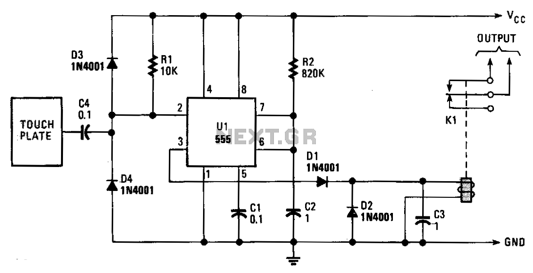
The monostable period is set for approximately 1 second, which is typical for this application. The induced line hum is transmitted through capacitor C2, resulting in a continuous stream of trigger pulses. The output remains low for about 10 milliseconds each second as the monostable times out and subsequently retriggers. Diode D1 and capacitor C3 serve to buffer the relay, preventing it from chattering due to those 10-millisecond pulses. Resistor R2 is responsible for setting the sensitivity. The relay activates when the plate is touched and deactivates up to one second after the finger is removed. The delay is dependent on the timing of the last retriggering of the monostable.
The circuit described operates using a monostable multivibrator configuration, which is commonly implemented with a timer IC, such as the 555 timer. In this setup, the monostable period is determined by an external resistor and capacitor, which define the timing characteristics. The chosen period of approximately 1 second allows for a substantial delay before the output returns to its stable state.
Capacitor C2 plays a crucial role in coupling the induced line hum into the circuit, ensuring that the multivibrator receives consistent trigger pulses. These pulses are essential for maintaining the operation of the relay, which is controlled by the output of the monostable multivibrator. The output of the circuit goes low for around 10 milliseconds every second, indicating that the monostable is in its timing phase. This short pulse duration is critical for preventing relay chatter, which can occur if the relay is activated and deactivated too rapidly.
Diode D1, in conjunction with capacitor C3, acts as a snubber circuit for the relay. This configuration ensures that the relay remains energized during the low output period, thus preventing any unintended toggling that could lead to mechanical wear or erratic behavior. The capacitor provides a temporary energy storage that smooths out the transitions, allowing the relay to maintain its state despite the brief interruptions.
Resistor R2 adjusts the sensitivity of the circuit. By varying this resistor, the threshold for trigger activation can be modified, allowing for fine-tuning based on the specific application and environmental conditions. This feature is particularly useful in scenarios where the induced noise levels may fluctuate.
The relay's operation is initiated when a conductive object, such as a finger, makes contact with the plate. This touch generates a trigger pulse that activates the relay. Once the finger is removed, the relay remains energized for a duration of up to one second, which is determined by the timing of the last retriggering of the monostable. This delay is beneficial in applications where it is necessary to maintain the relay's state briefly after the initial trigger to ensure that the connected load remains powered for a short period, providing a buffer against accidental disconnections.
Overall, this monostable relay circuit is designed for applications requiring a reliable and adjustable triggering mechanism with minimal noise interference, ensuring stable operation in various environments.The monostable period is set for about 1 second, as is the usual case. The induced line hum comes through C2, providing a continuous string of trigger pulses. The output becomes low for about 10 ms per second as the monostable times out and then retriggers. Diode D1 and capacitor C3 buffer the relay so it doesn"t chatter on those 10-ms pulses. Resistor R2 sets the sensitivity. The relay energizes when the plate is touched and de-energizes, up to one second after the finger is removed. The delay is a function of when the monostable last retriggered. 🔗 External reference