Line-voltage-monitor

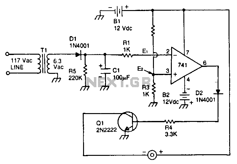
This circuit utilizes a type 741 operational amplifier (op amp) configured as a voltage comparator. One input of the 741 is connected to a reference voltage, sourced from a 12-V battery, via a resistor voltage divider. The voltage at the non-inverting input of the 741 is approximately 3 V. The inverting input of the op amp comparator is linked to the output of an 8-V line-operated power supply. In the event of an AC power failure, transformer T1 will no longer be energized, resulting in the discharge of the charge stored in capacitor C1 through resistor RS. When the voltage across the capacitor drops below the reference voltage of 3 V, the output of the comparator transitions to a high state. This output condition forward biases transistor Q1, activating the Sonalert to sound the alarm. The time constant of the R5/C1 combination is 22 seconds, which is sufficiently long to prevent noise from inadvertently triggering the alarm.
The circuit is designed to monitor the voltage levels and provide an alert in case of power failure. The 741 op amp serves as a voltage comparator, where the non-inverting input receives a stable reference voltage derived from a 12-V battery through a voltage divider network. This configuration ensures that the op amp can accurately compare the voltage from the capacitor against the reference voltage.
The inverting input of the op amp is connected to the output of an 8-V power supply. The operation of this circuit hinges on the behavior of capacitor C1, which is charged when the power supply is operational. Upon power failure, the capacitor begins to discharge through resistor RS, leading to a gradual decrease in voltage. The critical point of operation occurs when the voltage across C1 falls below the reference level of 3 V.
At this juncture, the output of the op amp switches to a high state, which is crucial for triggering the alarm system. Transistor Q1, which is used as a switch, is forward biased by this high output, allowing current to flow through the Sonalert, thereby sounding the alarm. The design incorporates a time constant formed by R5 and C1, calculated to be 22 seconds. This time constant is significant as it filters out transient noise in the power supply, ensuring that only genuine power failures will trigger the alarm, thus enhancing the reliability of the circuit in real-world applications.This circuit uses a type 741 op amp as a voltage comparator. One input of the 7.41 is connected to a reference voltage (a 12-V battery) through a resistor voltage divider. The potential at the noninverting input of the 741 is approximately 3 V. The inverting input of the op amp comparator is connected to the output of a line-operated 8-V power supply.
When the ac power main fails, T1 will no longer be energized, so the charge stored in capacitor C1 will begin to discharge through resistor RS. When the capacitor voltage drops below the reference voltage of 3 V, the output of the comparator becomes high. This output condition .will forward bias transistor Q1, causing the Sonalert to sound the alarm. The time constant of the R5/C1 combination is 22 seconds-long enough to prevent noise from triggering the alarm.