
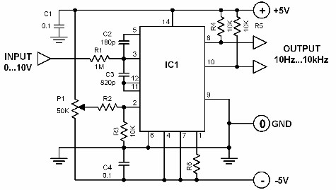
Linear frequency meter
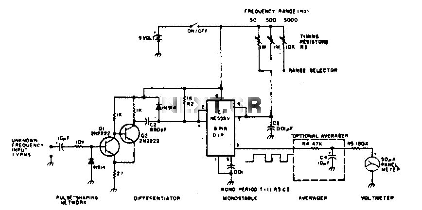
The 555 timer in a monostable configuration operates by producing a single output pulse in response to a triggering input. When the input signal transitions from a low to a high state, the timer is triggered, causing the output to switch from low to high for a predetermined duration, defined by external resistors and capacitors connected to the timer.
In this configuration, the time width of the output pulse (T) can be calculated using the formula:
\[ T = 1.1 \times R \times C \]
where \( R \) is the resistance in ohms, and \( C \) is the capacitance in farads. The output pulse width remains constant regardless of the duration of the trigger input, making it suitable for applications that require a consistent output signal.
The circuit typically includes a resistor connected between the discharge pin (pin 7) and the supply voltage (Vcc), and a capacitor connected between the threshold pin (pin 6) and ground. The trigger input is connected to the trigger pin (pin 2). Upon receiving a trigger pulse, the capacitor begins to charge through the resistor until it reaches approximately 2/3 of the supply voltage, at which point the output returns to its low state, and the capacitor discharges.
This monostable multivibrator configuration is widely used in timer applications, pulse generation, and as a switch for various electronic devices. Its ability to produce a precise output pulse in response to varying input frequencies makes it a versatile component in electronic design.The 555 is used in a monostable multivibrator circuit that puts out a fixed timewidth pulse which is triggered by the unknown input frequency. 🔗 External reference
Related Circuits
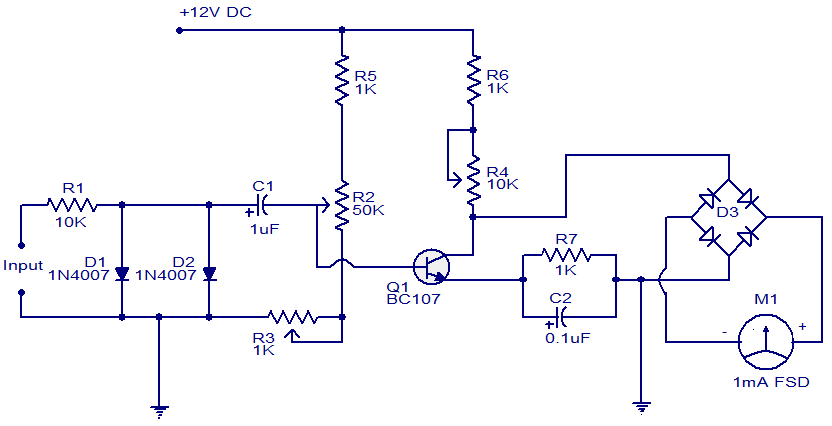
This is a simple circuit that functions as a tachometer. It operates as a frequency-to-current converter, transforming the incoming signal into a proportional current to drive the meter. The deflection on the ammeter correlates directly with the frequency of...
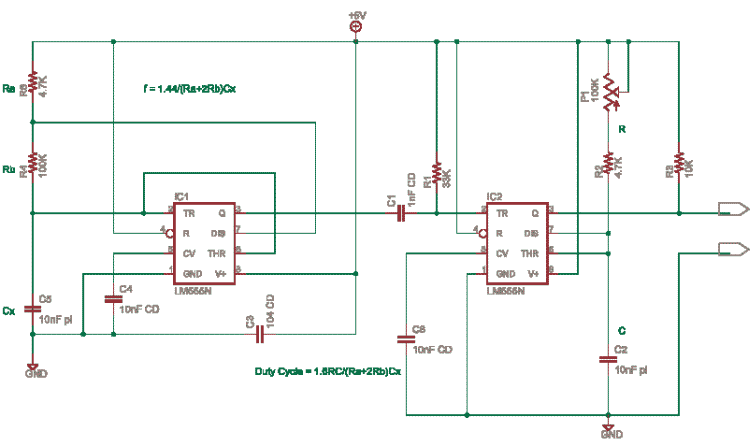
This circuit is based on an older application note from Exar. In this design, the frequency is determined by IC1, while IC2 and potentiometer P1 control the duty cycle. It is necessary to calculate the resistor (R) and capacitor...
One cannot expect high performance from a simple detector-based meter. The sensitivity is only sufficient to provide a basic understanding of the power output that the transmitter can achieve. A detector-based meter operates on the principle of rectifying the RF...
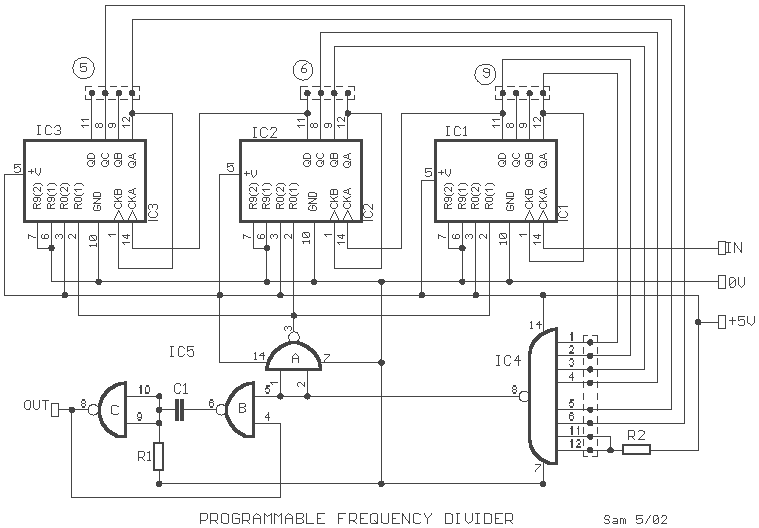
This circuit will divide the frequency of a TTL compatible square wave signal by a factor from 0 to 999. The circuit comprises three decade counters IC1 to IC3 and a few NAND gates. The three 7490s are cascaded...
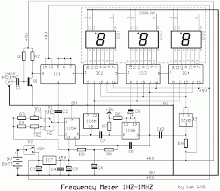
This circuit is a low-cost frequency meter that operates within the range of 1 Hz to 1 MHz. It utilizes an IC1 Schmitt trigger to regulate the input signal, adjusting it to a suitable level for IC2, IC3, and...
A voltage-to-frequency converter with a control range of 1:1000 can be constructed using the IC TSC9402. The specified component values in the circuit yield a conversion factor of 1 kHz per 1 V. Input voltages ranging from 10 mV...
Warning: include(partials/cookie-banner.php): Failed to open stream: Permission denied in /var/www/html/nextgr/view-circuit.php on line 713
Warning: include(): Failed opening 'partials/cookie-banner.php' for inclusion (include_path='.:/usr/share/php') in /var/www/html/nextgr/view-circuit.php on line 713