
Linear Inductance Meter Circuit
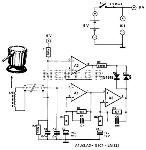
The described circuit leverages the relationship between inductance and the time constant in an RL circuit to provide a measurement of inductance via a digital voltmeter. In this configuration, the inductor is subjected to a step voltage, causing a current to rise according to the time constant determined by the inductance (L) and the resistance (R) in the circuit. The pulse width observed across the inductor is directly related to the inductance value, allowing for an indirect measurement.
To implement this circuit, the following components are typically required: an inductor whose inductance is to be measured, a resistor to form the RL circuit, a switch to apply a voltage pulse, and a digital voltmeter to read the resultant voltage across the inductor. The resistor value can be selected to ensure that the time constant (τ = L/R) is within a range that can be accurately measured by the DVM.
The output voltage across the inductor during the pulse will vary with the inductance value. As the inductance increases, the pulse width will also increase, which can be calibrated to correspond to specific inductance values. The DVM is used to capture this voltage, which can then be translated into a corresponding inductance value within the specified range of 5 to 250 uH.
For accurate readings, it is essential to account for factors such as the resistance of the leads, the characteristics of the inductor, and the response time of the DVM. Calibration against known inductance standards can also enhance measurement precision. Overall, this circuit provides a practical means to measure inductance in a non-invasive manner, suitable for various applications in electronics and testing environments. Using the fact that in an RL circuit, the pulse width seen across the inductor is proportional to the inductance, this circuit reads this indirectly on a DVM. The range is about 5 to 250 uH. 🔗 External reference
Related Circuits
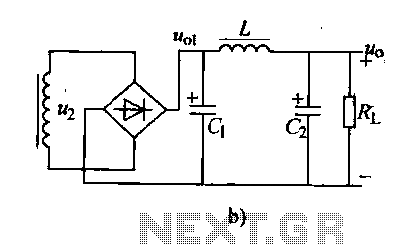
Analyzing the filter capacitance or inductance shows that the filtered DC output remains somewhat volatile. In situations requiring a smoother DC output, a duplex filter can be employed. The LC filter, which consists of a capacitor and inductor, is...
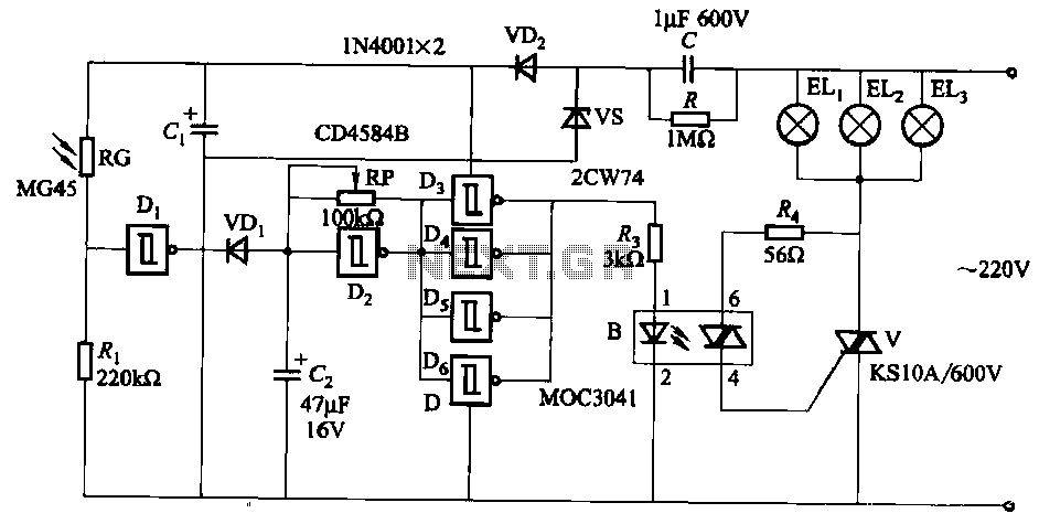
The circuit utilizes a CD4584B six Schmitt trigger integrated circuit (IC) with components Di and Ri forming a photometric circuit. D2, along with RP and C2, comprises an adjustable frequency ultra-low frequency oscillation device, where RP serves as an...
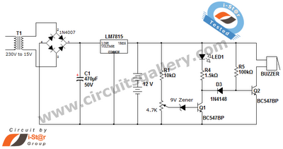
This is a straightforward 12V rechargeable smart battery charger circuit. It can be utilized as a charger for car batteries, inverter batteries, emergency light batteries, and more. An automatic indicator alarm circuit accompanies this battery charger schematic. The primary...
The circuit utilizes 60 individual LEDs to represent the minutes of a clock, along with 12 LEDs to indicate the hours. The power supply and timing circuitry are identical to those described in the previous 28 LED clock circuit....
DC Motor Control Using a Single Switch. This simple circuit allows for the operation of a DC motor in both clockwise and counterclockwise directions, as well as stopping it using a single switch. The circuit utilizes non-latching push button...
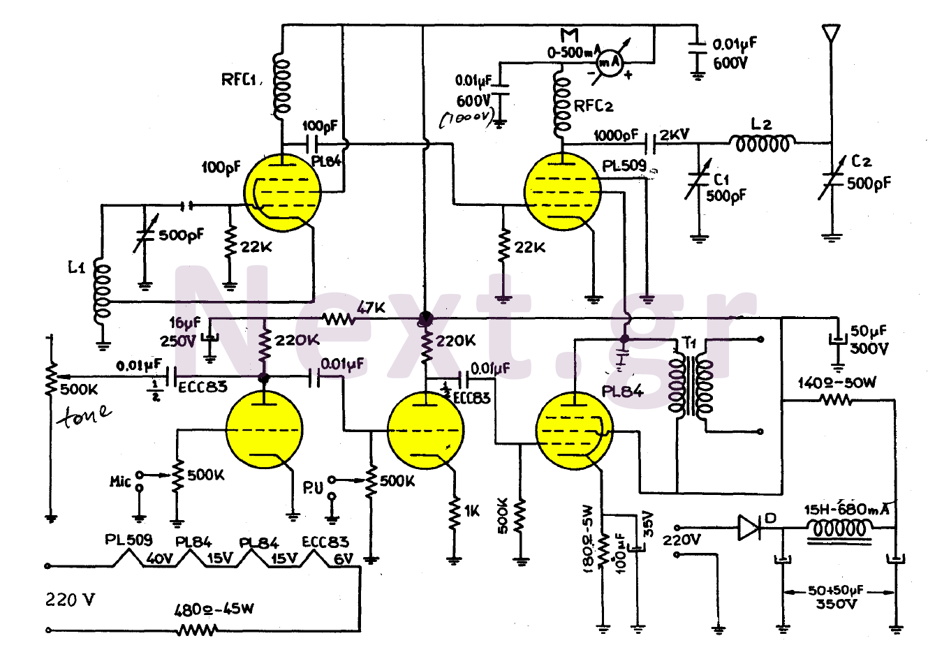
The simplicity of this transmitter, combined with its high performance, makes it particularly interesting. It has an output power of approximately 30 W, and under normal conditions, with the appropriate antenna and handling, it can achieve a range of...