
Linear temperature-to-frequency
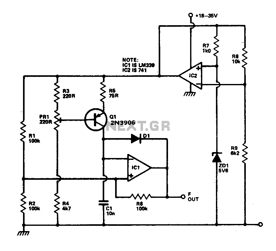
The described circuit operates by converting temperature variations into a corresponding frequency output, which can be effectively interfaced with digital systems. The linear frequency response of 10 Hz per °C makes it suitable for applications that require precise temperature monitoring and control. The temperature probe Q1, based on the bipolar junction transistor (BJT) principle, exploits the relationship between base-emitter voltage (Vbe) and temperature, where the Vbe decreases approximately 2 mV for each degree Celsius increase in temperature.
In this configuration, the constant current source maintains a steady current that flows through the temperature probe, ensuring that the voltage across it accurately reflects the temperature. Capacitor C1 serves as a timing element in conjunction with the Schmitt trigger, which provides hysteresis to the output signal, thus preventing noise from causing false triggering. The use of the 741 operational amplifier as a reference voltage source enhances the stability of the circuit, ensuring that variations in supply voltage do not affect the accuracy of the temperature readings.
The calibration process is critical for ensuring the accuracy of the circuit. By submerging Q1 in boiling distilled water, the output frequency can be set to a known reference point (1 kHz), allowing PR1 to be fine-tuned accordingly. This step ensures that the system can provide reliable temperature readings across the specified range. The inclusion of diode D1 allows for the rapid discharge of capacitor C1, which is essential for maintaining the responsiveness of the circuit to temperature changes.
Overall, this circuit design is advantageous for applications in environmental monitoring, industrial automation, and other fields where precise temperature measurement is crucial. Its integration with microprocessors and logic systems further enhances its versatility and usability in modern electronic systems.This circuit provides a linear increase of frequency of 10 Hz/°C over 0-100 °C and can thus be used with logic systems, including microprocessors. Temperature probes Ql Vbe changes 2 mV/°C. This transistor is incorporated in a constant current source circuit. Thus, a current proportional to temperature will be available to charge Cl. The circuit is powered via the temperature stable reference voltage supplied by the 741 Comparator ICl is used as a Schmitt trigger whose output is used to discharge Cl via Dl. To calibrate the circuit Ql is immersed in boiling distilled water and PR1 adjusted to give 1 kHz output. The prototype was found to be accurate to within 0 °C. 🔗 External reference
Related Circuits
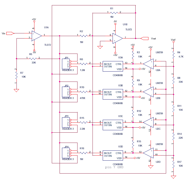
This circuit adjusts the gain of operational amplifier U1B in four distinct steps or segments. It is designed to achieve a linear output from various transducers at levels of 1%. Operational amplifier U1A serves as a buffering amplifier to...
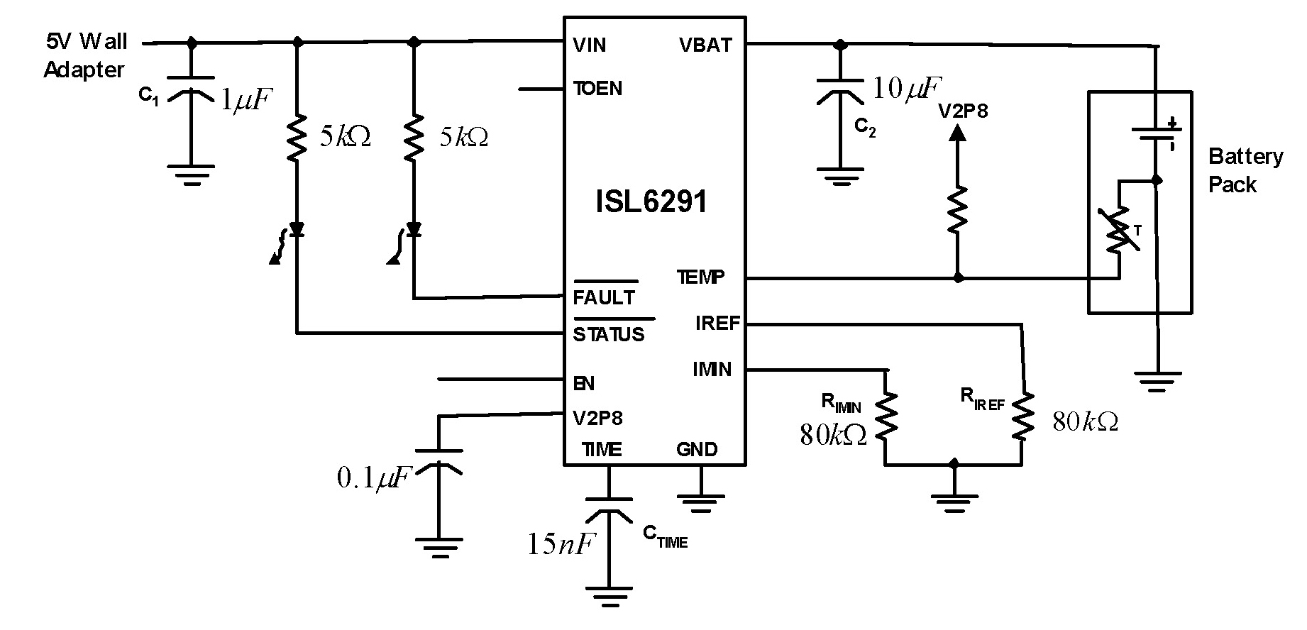
The ISL6291 offers a cost-effective integrated charger solution for single-cell lithium-ion and lithium polymer rechargeable batteries. This solution does not require any external pass elements, current sensing resistors, or reverse blocking diodes. The ISL6291 functions as a constant-current (CC)...
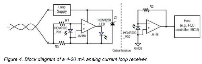
High linearity analog optocouplers offer the versatility needed to address a variety of analog isolation requirements. For high voltage applications, these optocouplers can effectively transmit analog signals between high voltage and low voltage areas without introducing distortion. This article...
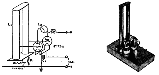
The use of a quarter-wave parallel-wire line as a tuning unit has been discussed in the chapter on Short-Lines, where it was pointed out that these circuits have comparatively high Q even at higher frequencies. Their significant length (approximately...
Operational amplifiers are the simplest and most effective means of executing a variety of linear functions, ranging from basic amplification to intricate analog computations. Operational amplifiers (op-amps) are versatile components widely utilized in electronic circuits for various applications. These devices...
It is widely recognized that power-saving regulations necessitate very low power consumption during standby conditions for all equipment continuously connected to mains power. In the standard version of the power supply, standby power consumption is approximately 9.0 W for...