
LM386 Audio Amplifier Chip
The described circuit utilizes an LM386 operational amplifier, which is a popular choice for audio amplification due to its simplicity and effectiveness. The gain control via terminals 1 and 8 allows for flexibility in adjusting the amplification level according to specific requirements. The choice of a 10 µF capacitor is crucial, as it influences the frequency response and stability of the amplifier.
In terms of input configuration, the differential input structure provided by terminals 2 and 3 ensures that the amplifier can effectively reject common-mode noise, enhancing the clarity of the amplified signal. Grounding terminal 2 stabilizes the input signal and allows for proper functioning of the amplifier.
The bypass terminal (terminal 7) is an important feature that can improve performance by reducing noise and enhancing stability. The inclusion of a capacitor at this terminal is a wise design choice, as it can significantly reduce the risk of oscillations that may arise in high-gain configurations.
The capacitors C1, C2, and C3 each serve distinct roles in the circuit. C1, as the gain-setting capacitor, directly influences the gain of the LM386. C2, the smoothing capacitor, is essential for filtering out power supply noise, contributing to a cleaner output signal. C3, acting as a current bank, plays a vital role in maintaining output stability during dynamic audio signals, ensuring that the amplifier can respond to sudden changes in current demand without distortion.
The LM386's ability to operate within a 4-12 volt DC range makes it versatile for various applications, from battery-operated devices to plug-in audio systems. The amplified output at terminal 5 can be directly connected to speakers or further processed through additional filtering stages to enhance audio quality.
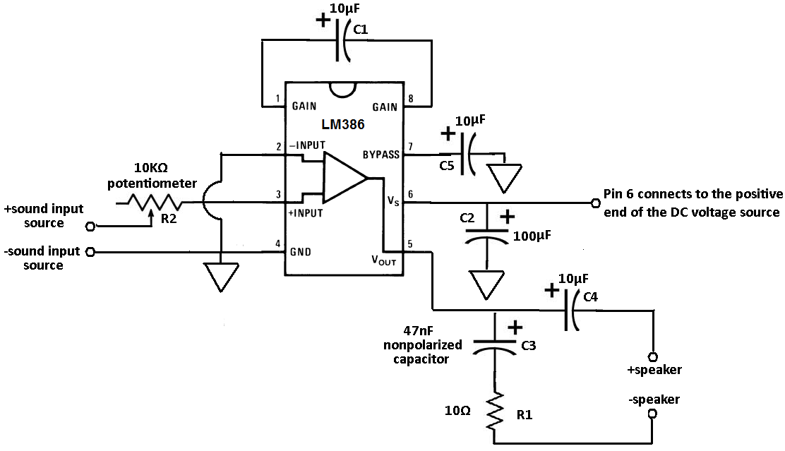
Overall, this amplifier circuit is designed to provide high-quality sound amplification while maintaining stability and minimizing noise, making it suitable for a range of audio applications.Terminals 1 and 8 represent the gain control of the amplifier. These are the terminals where you can adjust the gain by placing a resistor and capacitor or just capacitor between these terminals. In this circuit, we will place a 10G‚ µF capacitor between these terminals for the highest voltage gain.
Terminals 2 and 3 are the sound input signal ter minals. These are the terminals where you place the sound which you want to amplify. Terminal 2 is the -input and Terminal 3 is the +input. In our circuit, the positive sound signal will be placed on terminal 3 and terminal 2 will be tied to ground. Terminal 7 is the Bypass terminal. This can bypass 15KG resistors. This pin is usually left open or is wired to ground. However, for better stability, a capacitor is added in our circuit because this can prevent oscillations in the op amp chip.
C1 is a capacitor that is used to set the gain of the op amp. By placing a capacitor here, we can set the gain to the highest level to get maximum gain, which in this case is 200. Therefore, the voltage coming out of the op amp is 200 times the voltage going in. C2 is a smoothing capacitor. If the power supply has any abrupt voltage or current spikes, this capacitor works to smooth out the signal so that it evens out those spikes.
This capacitor helps to eliminate all of those ripples, which translates to the op amp having less noise input into it. C3 acts as a current bank for the output. This capacitor fills with electrons when demand for current is low and drains when sudden surges of current occur.
The LM386 amplifies the sound input into it by a factor of 200. All amplifiers need DC voltage in order to run. The LM386 takes anywhere from 4-12 volts of DC voltage to operate. The sound signal to be amplified are placed on terminals 2 and 3. The amplified sound signal then exits through terminal 5. After a few capacitors and a resistor to filter out unwanted noise that may be on this signal, we connect the speakers to play out the amplified sound. 🔗 External reference
Related Circuits

The 60-watt linear amplifier is a straightforward all-solid-state circuit utilizing the power MOSFET IRF840. The IRF series of power transistors is available in various voltage and power ratings, with a single IRF840 capable of handling a maximum power output...
This circuit is mainly intended to provide common home stereo amplifiers with a microphone input. Using a stereo microphone the circuit must be doubled. In this case, two separate level controls are better than a dual-ganged stereo potentiometer. Low...
Parts List The circuit consists of a preamplifier, tone controls, and a regulated DC power supply, providing a power output of 18 Watts for an 8 Ohm load. The circuit design includes three main components: a preamplifier, tone control circuitry,...
To complement the 60 Watt MOSFET audio amplifier, a high-quality preamplifier design was necessary. A discrete component topology, utilizing +24V and -24V supply rails, was selected, minimizing the transistor count while ensuring low noise, very low distortion, and a...
An active high-power tube operates in the MHz range, priced around 3 to 4 yuan, with a transition frequency (fT) exceeding one-fifth of 50 MHz for similar power tubes. This circuit is designed for high reliability in low-frequency high-power...
.gif)
This circuit utilizes a single integrated circuit (IC) along with a minimal number of external components to display audio levels through ten LEDs. The input voltage range is from 12V to 20V, with a recommendation for 12V. The LM3915...