
LM723 Current Limiting Questions
The LM723 voltage regulator is a versatile component widely used in power supply designs. It features current sense and current limit pins that play a critical role in protecting the circuit from excessive current conditions. The voltage at the current sense pin is monitored against a reference threshold (approximately 0.6 volts) at the current limit pin. When the voltage difference exceeds this threshold, the output of the error amplifier is driven low, which reduces the base drive to the series pass transistor, thereby limiting the output current.
In practical applications, the configuration of the sense resistor can significantly affect performance. The sense resistor is typically placed in series with the load, allowing for direct measurement of the current flowing through the circuit. However, it can also be positioned in the ground return path, which can simplify layout considerations but may introduce additional noise.
Thermal management is crucial in high-current applications. The LM723 can dissipate heat through the series pass transistor, which is responsible for regulating the output voltage. When selecting components, it is essential to consider the power ratings of resistors and transistors to ensure they can handle the expected thermal loads. The 0.1-ohm emitter resistors, which carry less current, will naturally dissipate less heat compared to the 0.47-ohm resistors, which experience higher current flow and therefore greater power dissipation.
For enhanced performance, particularly in low-ripple applications, it is advisable to consider modern alternatives, such as switching regulators, which can achieve higher efficiency and lower heat generation. A combination of a switch-mode pre-regulator followed by a linear regulator can provide the desired output characteristics while minimizing ripple and improving thermal performance.
The overall design must also account for temperature variations, as the voltage reference and resistor values can drift with temperature. Implementing a thermistor or temperature compensation circuit can help maintain stable operation across a range of environmental conditions.
In conclusion, while the LM723 is a reliable choice for many applications, assessing the specific requirements and considering newer technologies may yield better performance and efficiency in power supply designs.I get that the LM723 current sense and current limit pins (2 & 3) see a voltage created by the very low restistance current limiting resistors and that when this voltage reaches a certain value, the IC shuts down or limits the power supply output. How or where is thisvoltage parameter noted in the device specs I believe that I read somewhere that 0.
6 volts is the trigger point, but I can`t find anything like this in the spec sheet. What happens as this voltage reaches and exceeds 0. 6 volts Does the device reduce output voltage If so, does it do this until the voltage drops back to 0. 6 volts and stop there If you take a look at the equivalent circuit (on page 2) you will see that the current limit and current sense pins are simply tied to the base and emitter of an NPN transistor which has its collector tied to the output of the error amplifier.
Simply speaking, when the current limit pin of the 723 is more than 0. 6V more positive than the current sense pin, the output of the error amplifier is pulled low, reducing drive to the output series pass transistor. This may be done in a number of ways. The datasheet shows the sense resistor placed in the output prior to the voltage sensing, but it can also be done in the ground return.
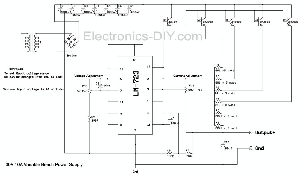
Table 2 on page 7 gives tot he formula for calculating the sense resistor value. Vsense is probably something like 0. 6V. but it may be specified somewhere. Note that it varies with temperature, the table on page 4 illustrates that. Okay, I`ll grant that the LM723 has been around for quite a while. Is there a similar, newer device that will do a better job for me This is a 22 volt, 10 amp, low ripple power supply. I`ve attached an article with schematic that I have built. It works reasonably well but even with 10, 000 mf filtering, I`m still getting about 0. 5 volts of ripple at 8 amps output. There are *many* newer chips. You might consider a switchmode pre-regulator followed by a linear regulator for the best thermal efficiency combined with reduced high frequency noise.
Also, I`ve played with the current limiting section (thanks for the help) by using a high quality multi-turn pot and monitoring the voltage across the current sensing pins. Sure enough when it reaches about 0. 6 volts, the output starts to drop rapidly. However, when I reduce the load, the output doesn`t come back by itself. Is this normal I notice that at full load, the 0. 1 ohm emitter resistors don`t get particularly warm, but the two paralleled 0. 47 ohm current limit resistors get hot as hell. Is this expected Let`s assume that full load is 8A through 4 transistors. So each of those 0. 1 ohm resistors has 2A flowing through it for a total power dissipation of 0. 4W per resistor. Now, each of the 0. 47 ohm resistors have 4A flowing through them, leading to a power dissipation of 7. 52 watts each. So they are dissipating about 20 times the amount of power. No wonder they get hotter. Then, whilst carefully monitoring the temperature of the output transistors, increase the load and monitor both the output current and voltage.
You should notice the output voltage fall and the current remain close to constant. On a power supply like this, a friend of mine had a thermistor attached to the pass transistor which pulled the current limit low if a preset temperature was exceeded. Another issue with the 723 is that it is seriously limited in power dissipation and this generally limits the output current to a relatively small value.
You may find that the 723`s output current needs to be monitored to ensure that you don`t exceed this at maximum current and minimum voltage - during short circuit conditions this is the worst case. Well, anyway, if there is a better LR and circuit that I should be using, I`d like to know about it. Or, if there are some improvements to this existing circuit, that`d be 🔗 External reference
Related Circuits
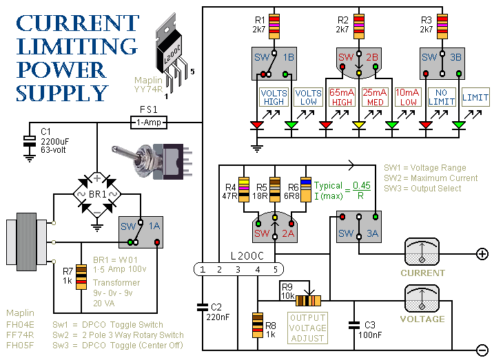
This is a 1-amp variable-voltage PSU. It adjusts from about 3v to 24v and has the added feature that you can limit the maximum output current. This is invaluable when, for example, you power-up a project for the first...
This circuit is utilized in RS-232 serial interface and current loop circuit applications. It converts voltage signals into a 20mA current signal, with a maximum transmission rate of 1200 bits per second. The CCD IC1 and transistor T1 form...
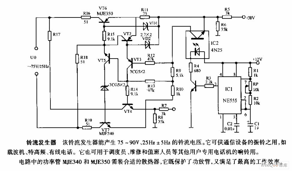
The ring current generator can produce a ringing current voltage of 75-90V and 25Hz ± 5Hz. It is suitable for use in vibrating rings in communication devices, such as carriers, ultrahigh frequency systems, and wire telephones. Additionally, it can...
This circuit is a two-wire light level detector, which does not separate the wires for power supply and output signal delivery. It operates using a current loop that performs both functions over a single pair of cables, requiring only...
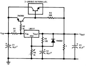
The LM117/LM317 from National Semiconductor Corporation is a three-terminal adjustable positive voltage regulator integrated circuit (IC). The output voltage range of the LM117/LM317 is from 1.2V to 37V with a load current capability of up to 1.5A. It is...
This circuit generates a constant current, constant voltage switched-mode power supply (SMPS). It is designed to efficiently charge a battery using a constant current, constant voltage approach. The circuit operates as a constant current, constant voltage SMPS, which is crucial...