
logic analyzer with old switch case power
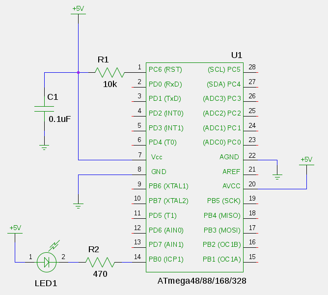
The Fabulous Logic Analyzer is a classic design that leverages the parallel port (LPT) of the laptop to capture and analyze digital signals. This design is particularly advantageous for hobbyists looking to implement basic logic analysis without the need for expensive equipment. The circuit typically consists of a series of input pins connected to the LPT port, which can read multiple digital signals simultaneously.
To build this logic analyzer, the following components are generally required: resistors to limit current, capacitors for signal smoothing, and a series of diodes to protect the circuit from voltage spikes. The logic analyzer can be powered through the LPT port, which simplifies the design further by eliminating the need for an external power source.
The software interface for the Fabulous Logic Analyzer can be developed using various programming languages that support parallel port communication, such as C or Python. This software will interpret the digital signals captured from the input pins and present them in a user-friendly format, allowing for easy analysis of timing and logic levels.
In summary, the construction of a DIY logic analyzer using an old Pentium III laptop and its LPT port is a practical project for electronics enthusiasts. It combines basic components with software development to create a functional tool for digital signal analysis.While ago, as an electronic hobbyist, I want a logic analyzer. Being a diy fan, I constructed a simple but efficient logic analyzer. I have old PIII laptop and which has one LPT port. So, I searched for simple design and found these. 1) The Fabulous Logic analyzer This is original design. But I prefer.. 🔗 External reference
Related Circuits
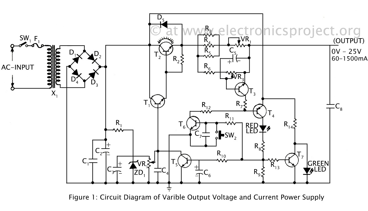
A ripple-free, short-circuit protected variable output voltage and current power supply is presented on this website as a verified project. The circuit diagram includes a description of various power supply circuits. This power supply circuit is designed to provide a...
A dual benefit for battery-powered portable devices is provided by Class D audio amplifiers. They produce much less power dissipation than their linear counterparts. Class D audio amplifiers, also known as switching amplifiers, are designed to achieve high efficiency and...
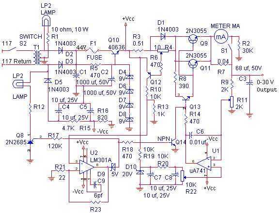
The linear power supply, shown in the schematic, provides 0-30 volts, at 1 amp, maximum, using a discrete transistor regulator with op-amp feedback to control the output voltage. The supply was constructed in 1975 and has a constant current...
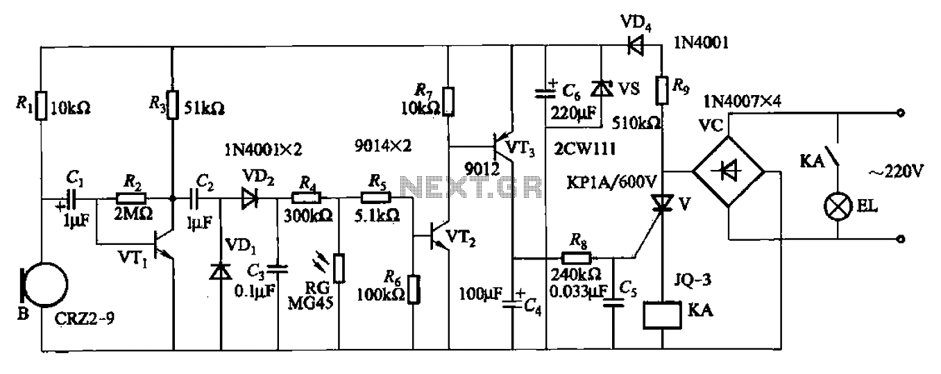
A resistor R8, capacitors Cd, and a thyristor V AC switch form a delay circuit. The lamp's lighting delay time is determined by the resistor Rs and capacitor C4, with a delay of approximately 40 seconds as indicated in...
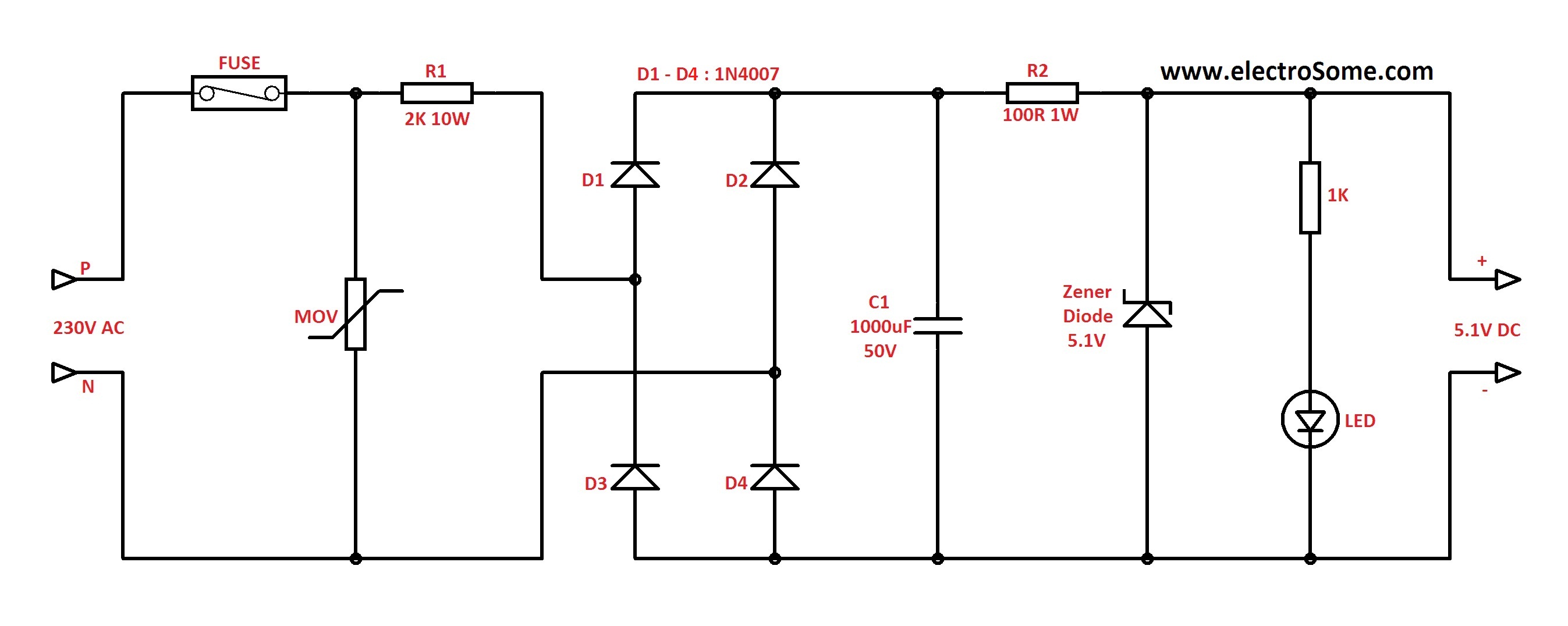
In Capacitor Power Supplies, a Voltage Dropping Capacitor is used in series with the phase line. Ordinary capacitors are unsuitable for these applications because mains spikes can create holes in the dielectric of standard capacitors, leading to failure. This...
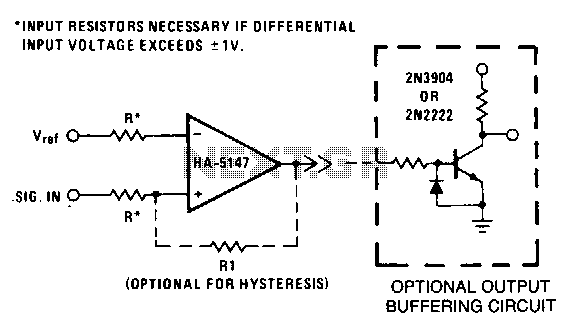
This circuit requires low noise, stable offset voltages, high open-loop gain, and high speed. These requirements are fulfilled by the HA5147. Standard variations of this circuit can be easily implemented using the HA-5147. For instance, hysteresis can be introduced...