
Logic Diagrams Services
Logic diagrams serve as essential tools in the field of electronics, providing a visual representation of how different components and systems interact through logical operations. The understanding of logic gates is fundamental to designing and troubleshooting electronic circuits. Each type of gate—AND, OR, and NOT—plays a pivotal role in digital logic design, allowing for the creation of complex circuits from simple building blocks.
For instance, the AND gate outputs a high signal only when all its inputs are high, making it crucial in applications where multiple conditions must be met simultaneously. The OR gate, on the other hand, produces a high output if at least one of its inputs is high, which is beneficial in scenarios requiring any one of several conditions to trigger an action. The NOT gate inverts the input signal, providing a simple yet powerful means of controlling outputs based on the absence of a signal.
In more advanced applications, the NAND and NOR gates expand the functionality of basic gates by combining their operations with NOT logic, leading to the development of universal gates capable of constructing any logical function. The COINCIDENCE gate further refines logic operations by introducing a requirement for a specific number of active inputs, which is particularly useful in complex systems requiring precise control.
As the complexity of circuits increases, the representation of multiple inputs becomes necessary. The methods demonstrated in Figure 4 highlight the adaptability of logic symbols to accommodate various configurations, ensuring clarity in communication among engineers and technicians. The use of standardized symbols, such as those defined by IEEE/ANSI, enhances consistency across diagrams, facilitating easier interpretation and collaboration among professionals in the field.
Overall, the mastery of logic symbols and their respective operations is critical for anyone involved in the design, analysis, or maintenance of electronic systems. Understanding these concepts not only streamlines the troubleshooting process but also empowers engineers to innovate and optimize circuit designs effectively.The use of logic symbology results in a diagram that allows the user to determine the operation of a given component or system as the various input signals change. To read and interpret logic diagrams, the reader must understand what each of the specialized symbols represent.
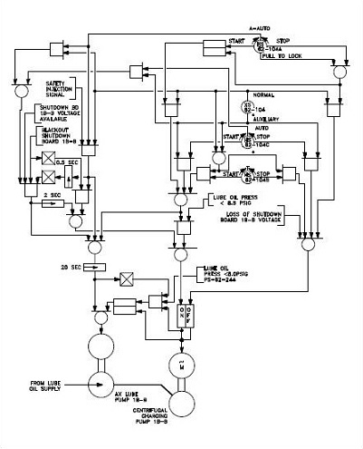
This chapter discusses the common symbols used on logic diagrams. When mastered, this knowledge should enable the reader to understand most logic diagrams. Facility operators and technical staff personnel commonly see logic symbols on equipment diagrams. The logic symbols, called gates, depict the operation/start/stop circuits of components and systems. The following two figures, which use a common facility start/stop pump circuit as an example, clearly demonstrate the reasons for learning to read logic diagrams. Figure 1 presents a schematic for a large pump, and Figure 2 shows the same pump circuit using only logic gates.
It is obvious that when the basic logic symbols are understood, figuring out how the pump operates and how it will respond to various combinations of inputs using the logic diagram is fast and easy, as compared to laboriously tracing through the relays and contacts of the schematic diagram for the same information. There are three basic types of logic gates. They are AND, OR, and NOT gates. Each gate is a very simple device that only has two states, on and off. The states of a gate are also commonly referred to as high or low, 1 or 0, or True or False, where on = high = 1 = True, and off = low = 0 = False.
The state of the gate, also referred to as its output, is determined by the status of the inputs to the gate, with each type of gate responding differently to the various possible combinations of inputs. Specifically, these combinations are as follows. Because the NOT gate is frequently used in conjunction with AND and OR gates, special symbols have been developed to represent these combinations.
The combination of an AND gate and a NOT gate is called a NAND gate. The combination of an OR gate with a NOT gate is called a NOR gate. Figure 3 illustrates the symbols covering the three basic logic gates plus NAND and NOR gates. The IEEE/ANSI symbols are used most often; however, other symbol conventions are provided on Figure 3 for information. The AND gate has a common variation called a COINCIDENCE gate. Logic gates are not limited to two inputs. Theoretically, there is no limit to the number of inputs a gate can have. But, as the number of inputs increases, the symbol must be altered to accommodate the increased inputs.
There are two basic ways to show multiple inputs. Figure 4 demonstrates both methods, using an OR gate as an example. The symbols used in Figure 4 are used extensively in computer logic diagrams. Process control logic diagrams usually use the symbology shown in Figure 2. The COINCIDENCE gate behaves like an AND gate except that only a specific number of the total number of inputs needs to be on for the gate`s output to be on. The symbol for a COINCIDENCE gate is shown in Figure 5. The fraction in the logic symbol indicates that the AND gate is a COINCIDENCE gate. The numerator of the fraction indicates the number of inputs that must be on for the gate to be on. The denominator states the total number of inputs to the gate. Two variations of the OR gate are the EXCLUSIVE OR and its opposite, the EXCLUSIVE NOR. The EXCLUSIVE OR and the EXCLUSIVE NOR are symbolized by adding a line on the back of the standard OR or NOR gate`s symbol, as illustrated in Figure 6.
Memory devices - 🔗 External reference
Related Circuits
It can be assumed that most 555 timer chips from various manufacturers are interchangeable due to their similar pin configurations. However, the programs or diagrams may simplify the pin arrangements, leading to potential confusion. Custom routing may be necessary...
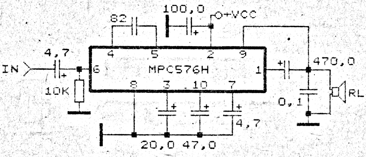
This amplifier circuit exhibits good sound quality. Although it does not provide high output power, it is capable of producing both soft and loud sounds reliably. The circuit utilizes a single IC, the MPC576H, along with several supporting components....
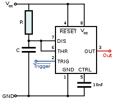
A battery-powered, pushbutton-triggered TTL/CMOS-compatible source of debounced 5V logic pulses is a simple but handy piece of test equipment to have in any tool kit. The circuit's battery-powered operation complicates what would otherwise be a trivial exercise in switch-bounce...
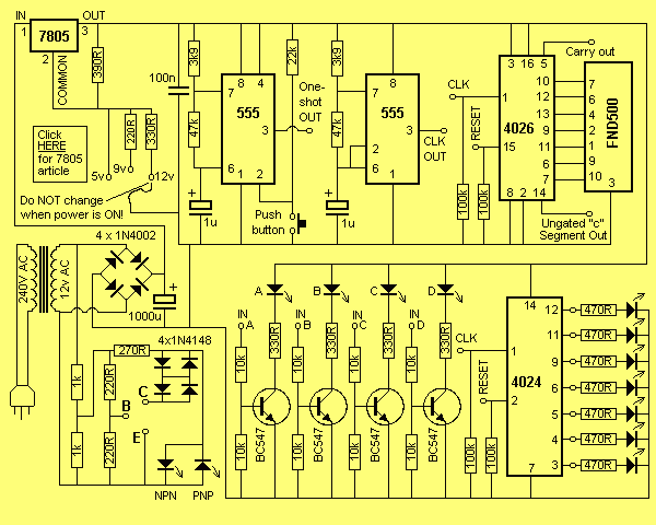
The logic designer is filled with features. It would not be possible to list all the possible combinations of the unit as the various building blocks on the board can be interconnected to obtain a wide variety of counting...
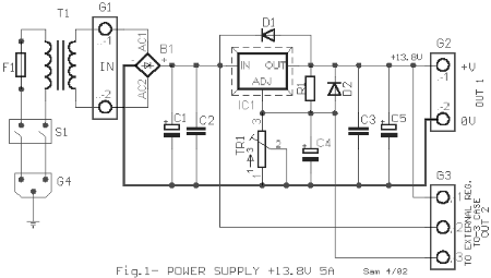
This AC to DC power supply can output 5A in continuous operation and 12A peak current. This type of DC power supply uses a PCB, allowing for two case types for IC1: TO-220 or TO-3. The regulation of this...
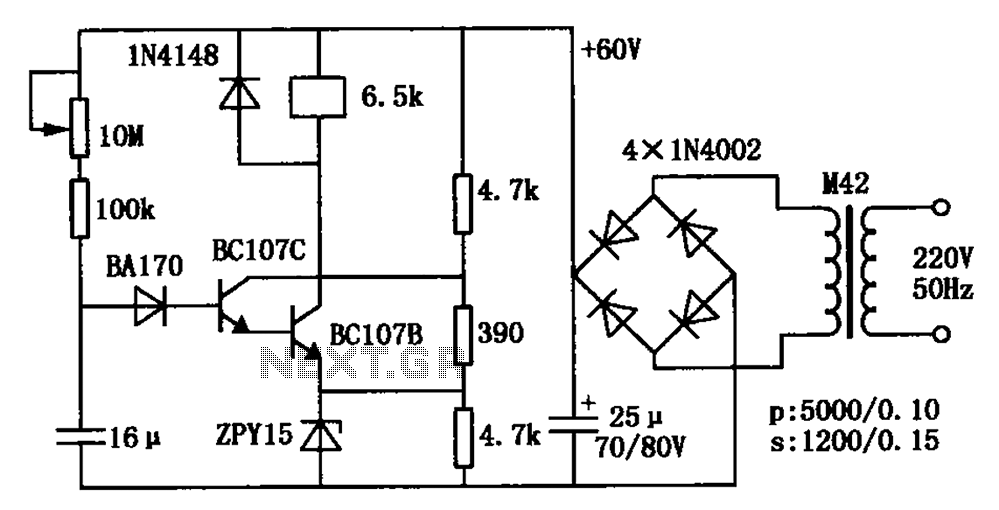
The circuit is a relay delay pull transistor configuration. Initially, when powered, the 16 µF capacitor has a voltage of zero, resulting in both transistors being off, and the relay remains inactive. As the 16 µF capacitor charges over...