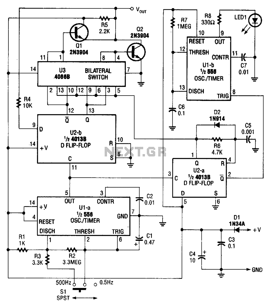
Logic-pulser

The pulser generates pulses at a user-selected frequency of 0.5 or 500 Hz, with a pulse width of about 5 ms. If the input to be pulsed is already being driven high or low by another output, the pulser automatically pulses the input to the opposite logic state. The pulser is powered by the circuit under test and operates from supplies of +5 to +15 V DC.
The pulser circuit is designed to provide reliable pulse generation for various electronic applications. The frequency selection between 0.5 Hz and 500 Hz allows for versatility in testing and controlling different types of circuits. The pulse width of approximately 5 ms ensures that the output signal is suitable for driving subsequent logic circuits or devices that require a brief activation period.
The circuit is configured to detect the current state of the input signal. If the input is already at a high logic level (logic '1'), the pulser will output a low logic level (logic '0'), and vice versa. This feature is particularly useful for interfacing with existing circuits without causing contention or damage to connected components.
Powering the pulser from the circuit under test allows for easy integration into various systems without the need for an external power supply. The operational voltage range of +5 to +15 V DC provides flexibility in design, accommodating different logic families and ensuring compatibility with a wide range of electronic devices.
In practical applications, the pulser can be utilized in testing scenarios where pulse modulation is required, such as in digital communication systems, timing circuits, and signal processing applications. The ability to switch the output to the opposite state enhances the functionality of the pulser, making it an essential tool for engineers and technicians in the field of electronics.The pulser generates pulses at a user-selected frequency of 0.5 or 500 Hz, with a pulse width of about 5 ms. If the input to be pulsed is already being driven high or low by another output, the pulser automatically pulses the input to the opposite logic state.
The pulser is powered by the circuit under test, and operates from supplies of from + 5 to + 15 V de.