Low-battery-protector-

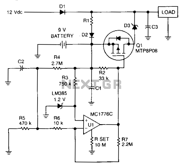
To prevent battery damage due to over-discharge, a low-voltage detector and switch should be included in the design of the battery backup circuit. The detector circuit should consume extremely low current. The switch should exhibit a low-voltage drop and be easy to control. R1 and D2 provide a trickle charge for the battery. Chosen for its low forward voltage drop, Schottky diode D3 prevents forward polarization of the diode incorporated in Q1. When the battery voltage is above approximately 8 V, the output of U1 is low and Q1 is turned on. If the battery voltage falls below 8 V, the output of U1 increases and turns off Q1.
In the proposed battery backup circuit, a low-voltage detection mechanism is critical to safeguard against over-discharge conditions that could lead to battery damage. The circuit incorporates a low-voltage detector that operates with minimal current draw, ensuring that the overall power consumption remains low, which is essential for battery-operated applications.
The low-voltage switch is designed to maintain a low-voltage drop, facilitating efficient operation. Resistor R1 and diode D2 are included in the circuit to provide a trickle charge to the battery, ensuring that it remains charged during periods of inactivity. The use of a Schottky diode, specifically D3, is advantageous due to its low forward voltage drop, which minimizes power loss and enhances efficiency. This diode also plays a critical role in preventing reverse bias conditions that could adversely affect the performance of transistor Q1.
The operational behavior of the circuit is defined by the voltage levels present at the battery. When the battery voltage is maintained above approximately 8 V, the output from operational amplifier U1 remains low, which keeps transistor Q1 in the 'on' state, allowing current to flow and the battery to be utilized effectively. Conversely, when the battery voltage drops below the 8 V threshold, the output of U1 transitions to a high state, which turns off Q1, thereby disconnecting the load and preventing further discharge of the battery. This design not only protects the battery from over-discharge but also enhances the longevity and reliability of the power source in the application.To prevent battery damage due to over -disc barge, a low-voltage detector and switch should be included in the design of the battery backup circuit. The detector circuit should consume extremely low current. The switch should exlnbit a low-voltage drop and be easy to control. R1 and D2 provide a trickle charge for the battery. Chosen for its low forward voltage drop, Schottky diode D3 prevents forward polarization of the diode incorporated in Ql.
When the battery voltage is above approximately 8 V, the output of U1 is low and Ql is turned on. If the battery voltage falls below 8 V, the output of U1 increases and turns off Ql.