
Low-battery-warning
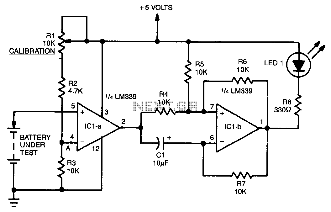
A voltage divider consisting of R1, R2, and R3 is utilized to establish the input reference voltage below which the batteries should be replaced. The reference voltage at point A is adjustable via R1. As illustrated in the diagram, a voltage range of 2 to 3.5 volts is achievable. When the battery voltage falls below the level at point A, the output of IC1a, which is part of an LM339 quad comparator, transitions from high to low. This change triggers IC1b, configured as an astable multivibrator. The time constant of the multivibrator is determined by feedback resistors R6 and R7 in conjunction with capacitor C1. The output from IC1b is connected to LED1 through dropping resistor R8. With the specified circuit values, the LED will flash at a frequency of 3 Hz. Although this circuit was specifically designed to monitor RAM backup batteries, it can be adapted for various applications requiring battery condition monitoring.
The described circuit employs a voltage divider formed by resistors R1, R2, and R3 to set a reference voltage that dictates the operational threshold for battery replacement. The adjustable resistor R1 allows for fine-tuning of the reference voltage at point A, enabling the circuit to accommodate different battery types or conditions. The LM339 quad comparator, specifically the IC1a configuration, serves as a vital component in monitoring the battery voltage. When the voltage at point A is exceeded by the battery voltage, the comparator output remains high; however, upon the battery voltage dropping below this threshold, the output switches to low, signaling a need for battery replacement.
The subsequent stage involves IC1b, which operates as an astable multivibrator. This configuration generates a square wave output, with the frequency controlled by the values of feedback resistors R6 and R7 and the timing capacitor C1. The specific choice of these components directly influences the flashing rate of the connected LED1, providing a visual indication of the battery's status. In this circuit, the output frequency is set to approximately 3 Hz, resulting in a noticeable flash rate for the LED.
The inclusion of resistor R8 serves to limit the current flowing through LED1, ensuring safe operation while providing adequate brightness. This design not only serves its primary function of monitoring RAM backup batteries but also offers versatility for adaptation in various battery monitoring applications. Adjustments to the resistor and capacitor values can tailor the circuit's response to different battery chemistries or operational requirements, thus broadening its utility in electronic systems where battery performance is critical.A voltage divider consisting of Rl, R2, and R3 is used to set the input reference voltage below which the batteries are to be replaced. That reference voltage, at point A, is varied by Rl. With the voltage divider shown in Fig. 9-7, a range of 2 to 3.5 Vis possible. When the battery voltage drops below that at point A, the output ol IC1a, 1/. of a LM339 quad comparator, switches from high to low. That triggers IC1b, which is configured as an astable multivibrator. Feedback resistors R6 and R7, coupled with capacitor Cl, determine the time constant of the multivibrator.
The output from IC1b is connected to LEDl through dropping resistor R8. With the circuit values as shown, the LED will flash at a rate of 3 Hz. Although this circuit was designed specifically to monitor RAM back-up batteries, it can of course be modified for use in just about any application where the condition of a battery must be found. 🔗 External reference