
Low Cost Metal Detector Circuit PCB
The metal detector circuit utilizes a BC548 transistor, which serves as the primary active component. This transistor is configured in a common-emitter arrangement, allowing it to amplify the signal generated by the oscillator. The circuit also includes a few passive components, such as resistors and capacitors, which are crucial for setting the oscillation frequency. The AM radio acts as a receiver for the oscillation signal, which is modulated by the presence of metal objects.
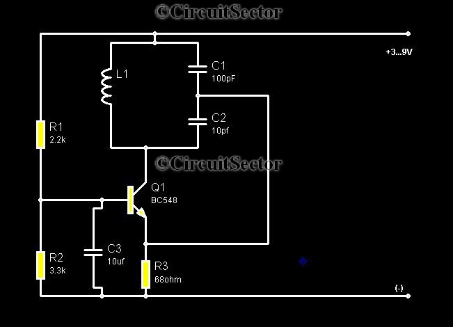
When constructing this circuit, the first step involves connecting the BC548 transistor in a way that it can generate oscillations. The base of the transistor is connected to a resistor that sets the biasing point, ensuring the transistor operates in the active region. The collector is linked to a tuned circuit, which consists of an inductor and a capacitor, forming a resonant circuit that determines the oscillation frequency.
The output from the collector is fed into the AM radio's input. Initially, when the circuit is powered, both the radio and the metal detector oscillator produce signals at the same frequency, leading to destructive interference and silence in the radio. To ensure proper operation, the frequency of the metal detector's oscillator must be fine-tuned to match the AM radio's tuned frequency.
When a metal object enters the detection zone, it alters the oscillation conditions of the circuit, disrupting the cancellation effect. This results in a change in the output signal, which the AM radio can detect, leading to the production of sound. The sensitivity of the metal detector can be adjusted by modifying the values of the passive components, allowing for detection of various types of metal objects at different distances.
This simple yet effective design demonstrates how basic electronic components can be utilized to create a functional metal detector, making it an excellent project for hobbyists and those interested in electronics.Metal detectors are usually very complicated and it may be consist of very costly components and metal detector DIY circuits are rare. However this metal detector hobby circuit can be constructed by only a few components such as BC548 and an ordinary AM radio that we usually use.
This metal detector schematic shown in the figure oscillates accordi ng to the frequency of any tuned AM radio. When the circuit powers up, the radio will not produce any sound because the radio oscillatory and the the metal detector oscillator will be in the same frequency and each will cancel itself. We all need to adjust the frequency of electronics circuit of metal detector to the tuned radio frequency.
Whenever a metal part come aside the circuit, the cancellation of two signals stops and the radio starts producing sound. 🔗 External reference
Related Circuits

The circuit diagram and detailed explanation of a simple aircraft radio circuit are provided below. The simple aircraft radio circuit typically consists of several key components that work together to facilitate communication between the aircraft and ground stations or other...

The following circuit illustrates a Bedside Lamp Timer Circuit Diagram. This circuit is based on the CD4060 integrated circuit. Features: An LED illuminates for approximately 25 seconds. The Bedside Lamp Timer Circuit utilizes the CD4060 IC, which is a versatile...
The LinkSwitch-TN supply LNK306PN provides a constant current output of up to 9 W at a maximum output voltage of 70 VDC, making it suitable for driving LEDs. A passive valley-fill power factor correction (PFC) circuit ensures the supply...
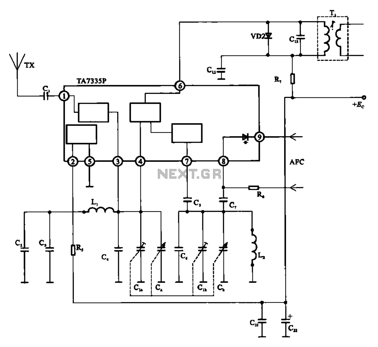
The FM front-end circuit, also referred to as an FM receiver circuit, is composed of discrete components. This configuration presents challenges in debugging and is prone to difficulties in miniaturization, leading to its gradual replacement by FM radio integrated...
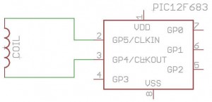
How to build your own RFID system using a microcontroller. This schematic is very simple. Building a Radio Frequency Identification (RFID) system using a microcontroller involves several key components and a straightforward schematic design. The essential elements of an RFID...
Various embodiments of the BB metal detector have been published, and it has been widely described in the press as a new genre. Instead of using a search and a reference oscillator as with BFO, or Tx and Rx...