
Low cost microwave field strength meter
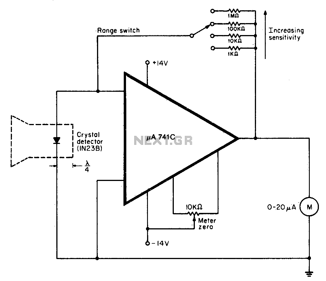
The described circuit involves a waveguide system that effectively channels electromagnetic energy towards a crystal detector, which is critical for applications in microwave frequencies, particularly within the X-band range (8 to 12 GHz). The waveguide, constructed from a 1-inch diameter plastic tubing, is designed with flared ends to minimize reflection losses and improve the coupling efficiency with the incoming signal.
The electroless copper coating applied to the inner surface of the plastic tubing serves to enhance the conductivity of the waveguide, allowing for efficient transmission of the microwave signals. This treatment is essential as plastic itself is an insulator, and the copper layer facilitates the propagation of the electromagnetic waves through the waveguide without significant attenuation.
For effective operation, the measurement device, or meter, must be calibrated. This is achieved by placing it in a known electromagnetic field or by comparing its readings with those of a calibrated reference meter. Calibration ensures that the readings obtained from the meter are accurate and reliable.
The operational procedure for utilizing the meter involves several steps. First, the meter should be pointed away from the signal source to avoid interference during calibration. The user must then select the desired measurement range on the device, which determines the sensitivity and scale of the readings. Adjusting the zero control is crucial to ensure that the meter reads zero when no signal is present, which establishes a baseline for subsequent measurements.
Once the meter is calibrated, the waveguide can be directed towards the signal source. The field strength can then be read directly from the meter, providing the user with real-time data on the strength of the electromagnetic field being measured. This setup is widely used in applications such as radar, telecommunications, and various research fields involving microwave technology.When operating, a waveguide directs energy onto a crystal detector. The diode shown is for X-band operation. The waveguide is a 1H inch piece of plastic tubing with the ends flared. The plastic is coated with an elec-troless copper solution to provide a conducting surface. The dimensions are not critical. For calibrated readings, the meter is placed in a known field or else compared to a calibrated meter To operate the meter, point it away from the signal. Switch the meter to the desired range, and adjust the zero control for a 0 reading. Then point the waveguide at the signal, and read field strength directly. 🔗 External reference
Related Circuits
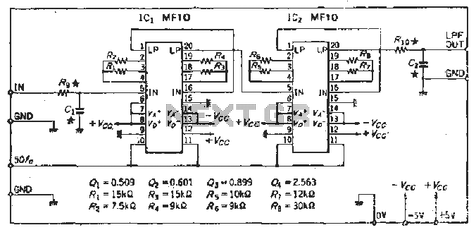
To create a Butterworth low-pass filter with a 12 dB/octave roll-off, four second-order (12 dB/oct) filter blocks are connected in series. This configuration is intended to achieve flat response characteristics across the frequency spectrum. The values for each stage...
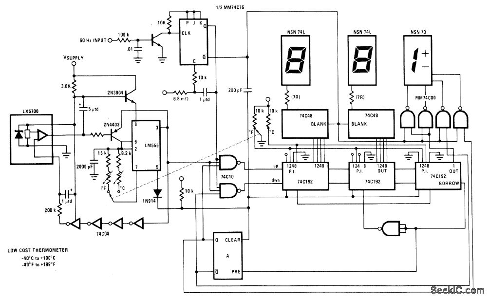
The National LX5700 temperature transducer supplies input to a code conversion circuit that drives a 3-digit LED display. This display indicates temperatures ranging from -40°F to +100°F or -40°F to +199°F, controlled by a ganged switch. The National LX5700...
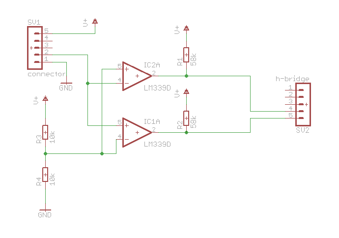
Here is a simple schematic of one of the components. The concept is that if the probed voltage is below half of the reference voltage, one LED will illuminate; otherwise, the second LED will turn on. Additionally, there is...
The circuit is capable of measuring frequencies ranging from 1.5 kHz to 500 kHz by connecting different capacitors, C1 to C6. It can handle a maximum frequency of up to 1 MHz. Transistor T1 serves as the integrator, with...
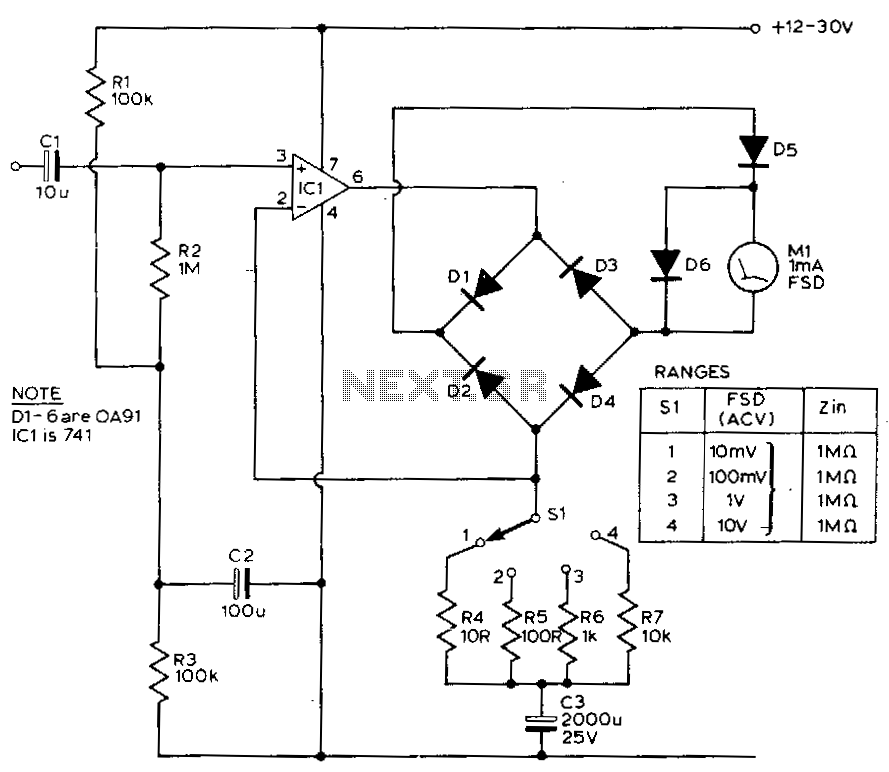
This circuit exhibits a flat frequency response from 8 Hz to 50 kHz, maintaining a -3 dB level at the 10 mV range. Furthermore, while the upper frequency limit remains consistent across less sensitive ranges, the lower frequency limit...
Using LM134 and LM10 integrated circuits, a thermometer can be constructed with a sensing range of -55 to 150 °C. The ideal meter for this circuit is a 0-200 µA. The proposed thermometer circuit utilizes the LM134, a current source...