
low distortion audio range oscillator
The sine wave oscillator is designed to produce high-quality sine wave outputs with minimal distortion across a wide frequency spectrum. The operational range of 16 Hz to 22 kHz makes it suitable for various applications, including audio signal generation, testing equipment, and waveform synthesis in electronic circuits.
The oscillator typically utilizes a feedback loop to maintain stability and accuracy in frequency output. Common configurations include the use of operational amplifiers or dedicated waveform generation ICs. Key components may include resistors, capacitors, and sometimes inductors, which are configured to set the desired frequency and shape of the output waveform.
For instance, a Wien bridge oscillator configuration can be employed to achieve low distortion. This configuration relies on a bridge circuit that balances the gain of the amplifier with the feedback network, allowing for stable oscillation. The frequency of oscillation can be adjusted by changing the values of the resistors and capacitors in the feedback loop.
In addition to low distortion, the design considerations should also account for power supply stability, temperature variations, and component tolerances, which can affect the output waveform quality. Proper PCB layout and grounding techniques are essential to minimize noise and interference, ensuring that the sine wave output remains clean and usable for high-fidelity applications.
Overall, this oscillator serves as a fundamental building block in various electronic systems where accurate sine wave generation is critical.Producing low-distortion sine waves, this oscillator operates over the range 16 to 22000 Hz.. 🔗 External reference
Related Circuits
This simple design features very low noise levels, approaching the theoretical minimum, high hum rejection, and variable gain controlled by a single rotary potentiometer. It resembles the circuitry used in many professional-grade mixing desks and can serve as the...
In an audio amplifier, the quality of sound depends on several factors, including the quality of active and passive components, circuit configuration, and layout. The selection of components is influenced by the constructor's budget. Discrete active components like transistors...
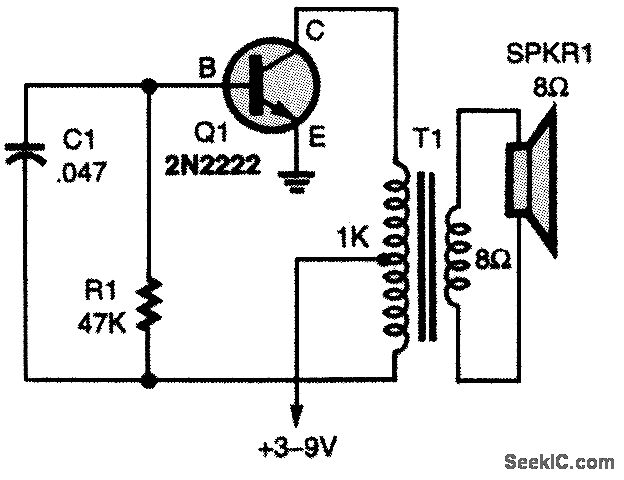
The oscillator circuit employs a center-tapped transistor output transformer that functions as a load for the collector of Q1, provides a feedback signal to the base, and acts as the output winding to drive the speaker. Resistor R1 supplies...
Unlike conventional small-signal methods, employing large-signal, time-domain design techniques facilitates the development of low-noise grounded-base oscillators suitable for VHF/UHF applications. The implementation of large-signal, time-domain design techniques in the creation of grounded-base oscillators represents a significant advancement in the field...
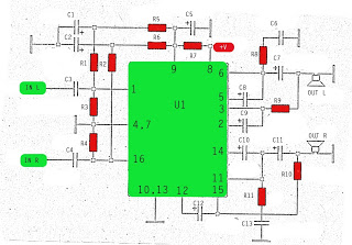
The amplifier circuit utilizes the STK integrated circuit, similar to a previous design. This circuit features two inputs and two outputs, commonly known as a stereo amplifier. It is a power amplifier rated at 2 x 18 Watts with...
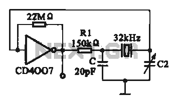
A 32 kHz clock oscillator is essential for digital circuits, as depicted in the schematic. The 32 kHz crystal clock oscillator serves to provide a time reference signal for the digital circuit. It utilizes a CMOS integrated circuit, specifically...
Warning: include(partials/cookie-banner.php): Failed to open stream: Permission denied in /var/www/html/nextgr/view-circuit.php on line 713
Warning: include(): Failed opening 'partials/cookie-banner.php' for inclusion (include_path='.:/usr/share/php') in /var/www/html/nextgr/view-circuit.php on line 713