
Low-flow-rate-thermal-flowmeter
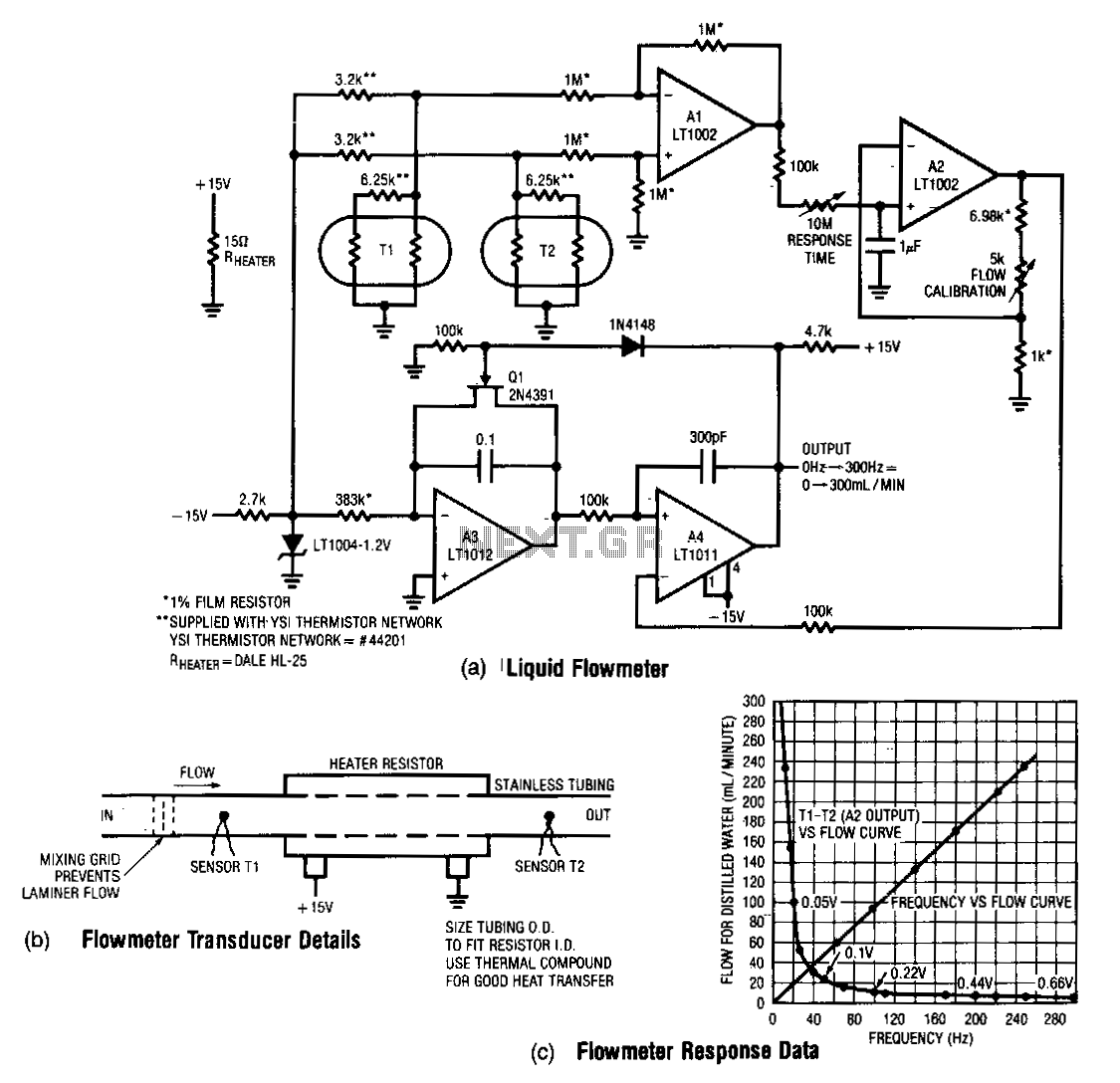
This design measures the differential temperature between two sensors. Sensor T1, located before the heater resistor, measures the fluid's temperature prior to heating by the resistor. Sensor T2 detects the temperature rise induced in the fluid by the resistor's heating. The difference signal from the sensors is outputted at A1. A2 amplifies this difference with a time constant determined by the 10 MΩ adjustment. The output of A2 is depicted in Fig. 33-1c, showing an inverse relationship with flow rate. A3 and A4 linearize this relationship while simultaneously providing a frequency output.
A3 operates as an integrator that is biased by the LT1004 and the 338 kΩ input resistor. Its output is compared to the output of A2 at A4. Large inputs from A2 cause the integrator to run for an extended period before A4 can increase, which activates Q1 and resets A3. For smaller inputs from A2, A3 does not need to integrate for long before the resetting action occurs. Consequently, this configuration oscillates at a frequency that is inversely proportional to the output voltage of A2. Since this voltage is inversely related to flow rate, the oscillation frequency corresponds linearly to the flow rate.
The circuit design incorporates two temperature sensors, T1 and T2, positioned strategically to capture the thermal dynamics of the fluid system. Sensor T1 is situated upstream of the heater resistor, providing a baseline temperature reading of the fluid prior to any thermal influence. Conversely, sensor T2 is positioned downstream, where it registers the elevated temperature resulting from the heating process. The differential temperature, calculated as the output from A1, serves as a critical parameter for the subsequent signal processing stages.
Amplification of the differential signal is performed by operational amplifier A2, which is configured with a time constant defined by a 10 MΩ resistor. This configuration allows for precise adjustment of the amplifier's response to varying temperature differentials, ensuring that the output accurately reflects the changes in fluid temperature as influenced by flow rate. The inverse relationship between the output of A2 and flow rate is illustrated in the referenced figure, indicating that as flow rate increases, the output voltage decreases.
The integration process is handled by A3, which is designed to accumulate the signal from A2 over time. The biasing provided by the LT1004 and the input resistor of 338 kΩ ensures that A3 operates within optimal parameters. The output of A3 is then compared to the output of A2 at A4. This comparison is crucial, as it determines when the integrator needs to reset. Large signals from A2 lead to prolonged integration times, allowing for a gradual build-up before triggering the reset mechanism via Q1. In contrast, smaller signals result in quicker resets, promoting an oscillatory behavior in the circuit.
The oscillation frequency produced by this configuration is of particular importance, as it is inversely proportional to the output voltage from A2. This relationship establishes a direct correlation between the oscillation frequency and the flow rate, enabling the circuit to provide a frequency output that can be easily interpreted and utilized for flow measurement applications. The overall design effectively combines temperature sensing, signal amplification, integration, and frequency output generation into a cohesive system for monitoring fluid dynamics.This design measures the differential temperature between two sensors. Sensor Tl, located before the heater resistor, assumes the fluid"s temperature before it is heated by the resistor. Sensor TZ picks up the temperature rise induced into the fluid by the resistor"s heating. The sensor"s difference signal appears at Al"s output. A2 amplifies this difference with a time constant set by the 10 MO adjustment. Fig. 33-lc shows AZ"s nutput versus flow rate. The function has an inverse relationship. A3 and A41inearize this relationship, while simultaneously providing a frequency output. A3 functions as an integrator that is biased from the LT1004 and the 338-KO input resistor. Its output is compared to AZ"s output at A4. Large inputs from A2 force the integrator to run for a long time beforeA4 can increase, turning on Ql and resetting A3. For small inputs from A2, A3 does not have to integrate long before resetting action occurs. Thus, the configuration oscillates at a frequency which is inversely proportional to AZ"s output voltage.
Since this voltage is inversely related to flow rate, the oscillation frequency linearly corresponds to flow rate. 🔗 External reference