
Low-frequency-converter
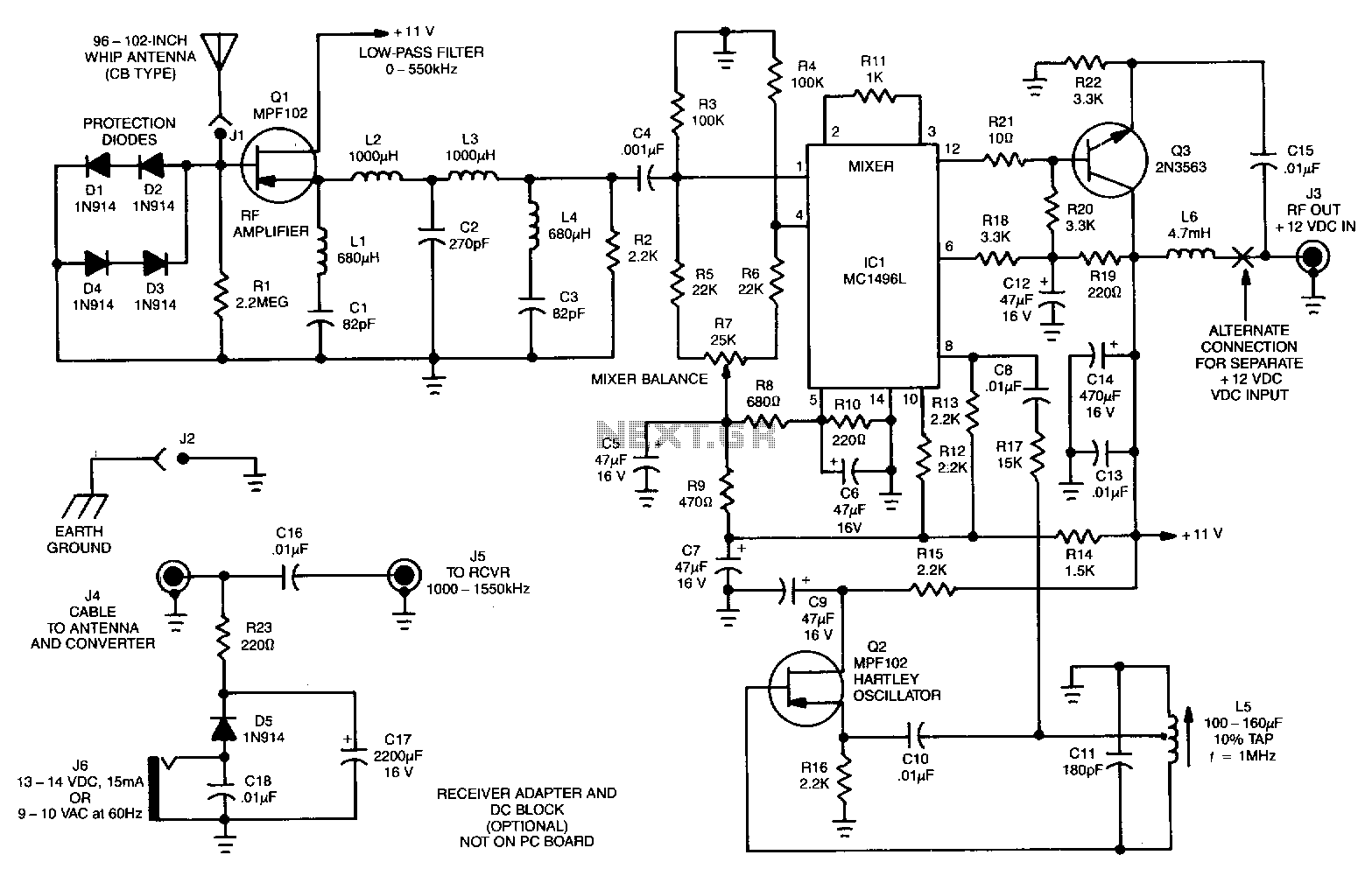
The signals below 550 kHz include maritime mobile, distress signals, radio beacons, aircraft weather information, European Longwave-AM broadcasts, and point-to-point communications. A low-frequency converter transforms the 10 to 500 kHz LW range into a 1010 to 1550 kHz MW range by adding 1000 kHz to all received signals. Radio calibration is not required because signals are received at the AM radio's dial setting plus 1 MHz; for instance, a 100 kHz signal is received at 1100 kHz, and a 335 kHz signal at 1335 kHz. The low-frequency signals are directed to IC1, a doubly-balanced mixer.
Transistor Q2 and its associated circuitry create a Hartley 1000 kHz local oscillator, which is coupled from Q2's drain through capacitor C8 to pin 8 of IC1. Signals within the 10-550 kHz range are converted to 1010-1550 kHz. The mixer heterodynes the incoming low-frequency signal with the local oscillator signal. Transistor Q3 lowers IC1's high output impedance to approximately 100 ohms to match most receiver inputs. Capacitor C15 couples the 1010-1550 kHz frequencies from Q3's emitter to output jack J3 while blocking any DC bias. Inductor L6 couples the DC voltage carried in the RF signal cable from the receiver/DC adapter. The DC voltage and RF signals do not interfere with each other, eliminating the need for a separate power supply wire, thereby simplifying installation at remote locations. Capacitors C14 and C13 provide DC supply filtering. The kit is available from North Country Radio, P.O. Box 53, Wykagyl Station, NY 10804.
The described circuit is designed for the reception and conversion of low-frequency radio signals into a more manageable medium-wave frequency range. The low-frequency converter is essential for applications that require monitoring maritime and aviation communications, as well as other critical low-frequency signals. The use of a doubly-balanced mixer (IC1) allows for efficient signal processing, enabling the conversion of incoming low-frequency signals into a higher frequency range suitable for AM radio reception.
The local oscillator, created by transistor Q2, is pivotal for the mixing process, providing a stable frequency reference that is necessary for accurate signal conversion. The Hartley oscillator configuration is chosen for its simplicity and reliability, ensuring that the local oscillator operates at a consistent frequency of 1000 kHz. The coupling of the oscillator output to the mixer through capacitor C8 ensures that the appropriate frequency components are fed into the mixer without introducing unwanted DC bias.
Transistor Q3 plays a critical role in impedance matching, which is essential for maximizing power transfer to the receiver. The output impedance of the mixer is reduced to approximately 100 ohms, which is compatible with most radio receivers, ensuring that the converted signals are effectively transmitted to the output jack (J3). Capacitor C15 serves to couple the high-frequency output while blocking any DC components, preserving the integrity of the RF signal.
Inductor L6 is strategically placed to allow the DC voltage from the receiver/DC adapter to be carried alongside the RF signals without interference. This design choice simplifies the wiring requirements for remote installations, making the system more user-friendly and reducing the complexity of setup.
Overall, this circuit design exemplifies efficient signal processing techniques in radio frequency applications, ensuring reliable reception and conversion of low-frequency signals into a usable format for radio communication. The inclusion of filtering capacitors (C14 and C13) further enhances the performance of the power supply by reducing noise and ensuring stable operation. The availability of the complete kit from North Country Radio facilitates easy access for enthusiasts and professionals looking to implement this technology in their projects.Among the signals below 550 kHz are maritime mobile, distress, radio beacons, aircraft weather, European Longwave-AM broadcast, and point-to-point communications. The low-frequency converter converts the 10 to 500kHz LW range to a 1010 to 1550kHz MW range, by adding 1000kHz to all received signals.
Radio calibration is unnecessary because signals are received at the AM-radio"s dial setting, plus 1 MHz; a 100-kHz signal is received at llOO kHz, a 335-kHz signal at 1335 kHz, etc. The low-frequency signals are fed to IC1, a doubly-balanced mixer. Transistor Q2 and associated circuitry form a Hartley 1000-kHz local oscillator, which is coupled from Q2"s drain, through C8, to IC1 pin 8. Signals in the 10-550 kHz range are converted to 1010-1550 kHz. The mixer heterodynes the incoming low-frequency signal and local-oscillator signal. Transistor Q3 reduces IC1"s high-output impedance to about 100 !l to match most receiver inputs. Capacitor Cl5 couples the 1010-1550 kHz frequencies from Q3"s emitter to output jack ]3, while blocking any de bias.
Inductor L6 couples tire de voltage that"s carried in the rf signal cable from the rcvr/dc adaptor. The de voltage and rf signals don"t interfere with one another; that saves running a separate power-supply wire, which simplifies installation at a remote location. Capacitors Cl4 and Cl3 provide de supply filtering. The kit is available from North Country Radio, P.O. Box 53, Wykagyl Station, NY 10804. 🔗 External reference