
Low Ohms Adaptor For DMMs Based On An LM317 Regulator
The described adapter circuit serves as a reliable constant current source suitable for measuring low resistances with high precision. The LM317 regulator is a versatile component that, when configured correctly, can provide a stable output current regardless of variations in load resistance, making it ideal for this application. The use of a low-value resistor allows for the measurement of small resistances, which is crucial in many electronic testing scenarios.
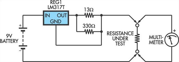
The circuit design includes two resistors: one connected between the output and adjustment pins of the LM317, and the other serving as a load. The resistor values should be selected to ensure that the output current remains at the desired 100mA level. The output voltage across the load resistor can be calculated using Ohm's law (V = I × R), which, given the constant current, allows for straightforward resistance calculations based on the measured voltage.
The choice of a plastic enclosure for the circuit enhances portability while protecting the components from environmental factors. The absence of an on/off switch simplifies the design and reduces the risk of accidental operation, as the circuit only draws current when a load is connected.
For improved accuracy, the circuit can be calibrated by adjusting the resistor values based on the actual current measured. This calibration ensures that the output current remains consistent, which is critical for precise resistance measurements. Furthermore, users should be aware of the potential risks associated with connecting the adapter to sensitive components, as the output voltage and current could exceed the ratings of certain devices, leading to damage. Proper precautions should be taken to avoid applying the full output voltage to the multimeter when it is set to a low voltage range, ensuring safe and effective operation of the adapter circuit.This adaptor circuit is essentially a 100mA constant current source. It is applied across a low-value resistor of unknown value (ie, the resistance to be measured) and the resulting voltage drop can then be measured by a digital multimeter (DMM). Setting your DMM to the 200mV range will enable it to measure up to 2O with high resolution while the
2V range will give a maximum resistance measurement of 20O. Construction could consist of mounting the LM317 adjustable 3-terminal regulator inside a small plastic box together with the battery and two resistors connected to the output and Adj pins. No on/off switch is required since no current will be drawn when no external resistance is connected across the Test terminals.
Accuracy using 1% resistors should be within 5% and this could be improved by measuring the current, adjusting the resistance between the output and Adj pins of the LM317 to provide a precise 100mA. Before using the adaptor, check that your meter is not likely to be damaged by having the full output (6V+) applied when it is set to a low voltage range.
Similarly, be aware that the voltage and current output of the adaptor may damage components if you use it for "in-circuit" tests. 🔗 External reference
Related Circuits
The motor vehicle currently represents a no-emission automotive solution, serving as a green means of transportation that is expected to significantly impact human society in the 21st century. The direct-flow brushless electric machine has emerged as a leading technology...
Interest in creating an antenna rig suitable for use with a handheld transceiver for fox hunting. Suggestions are sought for a cost-effective yet efficient solution. To create an effective antenna rig for fox hunting using a handheld transceiver (HT), several...
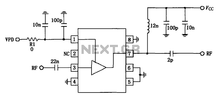
836MHz RF2347 low noise amplifier circuit diagram. The RF2347 is a low noise amplifier (LNA) designed for operation at a frequency of 836 MHz. It is typically used in RF applications where signal amplification is critical, such as in communication...
This circuit was designed to provide a 5 V output from a 24 V battery of a solar-powered generator. While solar power is essentially free, it is crucial to avoid waste, especially in small installations; if the battery depletes...
This is an old project from approximately three years ago. It was initiated when I was eight years old, after my father purchased a Commodore 64 for me twenty-eight years ago, and the excitement of that moment remains vivid. The...
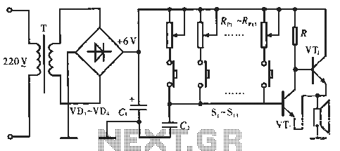
The circuit includes resistors Rp1 to Rp13, which serve dual purposes: they scale the resistance for the keyboard and function as timing resistors for the oscillator. Capacitor C2 acts as a wide discharge capacitor, while switches S1 to S13...
Warning: include(partials/cookie-banner.php): Failed to open stream: Permission denied in /var/www/html/nextgr/view-circuit.php on line 713
Warning: include(): Failed opening 'partials/cookie-banner.php' for inclusion (include_path='.:/usr/share/php') in /var/www/html/nextgr/view-circuit.php on line 713