Low-power-inverter

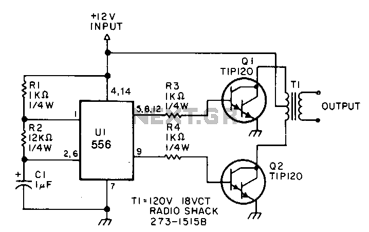
This low-power inverter utilizes only nine components to convert 10 to 16 VDC into a 60 Hz, 115 V square-wave output suitable for operating AC equipment with a maximum power of 25 W. The initial section of the 556 timer chip is configured as an astable oscillator, with resistors R2 and capacitor C1 determining the frequency. The output is accessible at pin 5. The second section functions as a phase inverter, with its output available at pin 9. Resistors R3 and R4 prevent output transistors Q1 and Q2 from loading down the oscillator.
The two transistors operate in a push-pull configuration to drive the transformer. When one transistor is in the on state, the other is in the off state. The transformer used is a 120 V/18 VCT unit that is connected in reverse, allowing it to step the voltage up instead of down. The oscillator circuit, comprising U1, R1, R2, and C1, operates effectively within a voltage range of approximately 4 to 16 V, providing a stable output.
This inverter circuit is designed to efficiently convert low DC voltage into a usable AC voltage, making it suitable for various applications where small power requirements exist. The astable oscillator configuration allows for continuous oscillation, generating a square wave at the desired frequency. The phase inverter section ensures that the output transistors alternately switch on and off, creating the necessary alternating current for the transformer.
The push-pull operation of the transistors is critical for maintaining the efficiency of the inverter. By ensuring that only one transistor conducts at a time, the circuit minimizes energy loss and heat generation. The transformer, connected in reverse, takes advantage of the alternating current generated by the transistors to step up the voltage to the required level for AC equipment.
Overall, this circuit exemplifies a simple yet effective design for a low-power inverter, utilizing minimal components while providing stable and reliable output to drive small AC loads. The use of a 556 timer chip simplifies the design while ensuring consistent performance over a range of input voltages.This low-power inverter uses only 9 parts and turns 10 to 16 Vdc into 60-Hz, 115-V square-wave power to operate ac equipment up to 25 W. The first section of the 556 timer chip is wired as an astable oscillator with R2 and C1 setting the frequency.
The output is available at pin 5. The second section is wired as a phase inverter. That output is available at pin 9. Resistors R3 and R4 keep output transistors Q1 and Q2 from loading down the oscillator. The two transistors drive the transformer push-pull fashion. When one transistor is biased-on, the other is cut-off. The transformer is a 120 V/18 VCT unit that is connected backwards, so that it steps the voltage up rather than down. Oscillator circuit U1, R1, R2, and C1 operates from about 4 to 16 V with a very ~stable output.