
Low power monostable circuit diagram
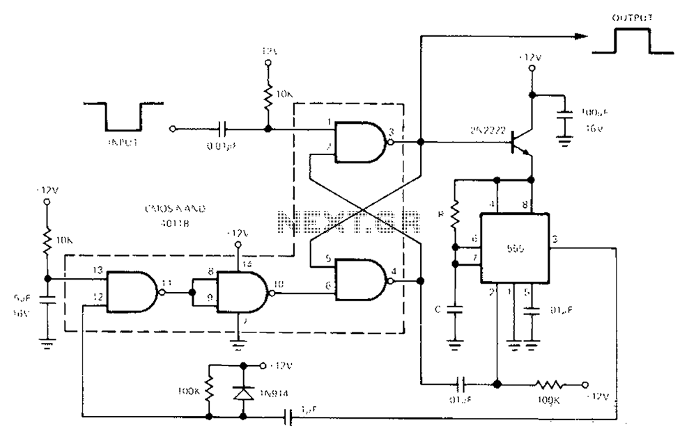
The 555 Timer is a versatile integrated circuit commonly used in timer, delay, pulse generation, and oscillator applications. In a single-shot configuration, it operates as a monostable multivibrator, generating a precise output pulse in response to a triggering event. The CMOS4011B NAND gate can be utilized in conjunction with the 555 Timer to create complex logic functions or signal processing tasks, enhancing the circuit's functionality.
In this configuration, the standby power consumption of less than 50 µA ensures that the circuit remains energy-efficient, making it suitable for battery-operated devices. When the one-shot circuit is activated, the current consumption rises to 4.5 mA, which is necessary for driving the output load during the pulse duration. The pulse width, determined by the equation T = 1.1RC, allows for precise control over the timing characteristics of the output signal, where R is the resistance in ohms and C is the capacitance in farads.
This arrangement provides a reliable solution for applications requiring timed events or controlled signal generation, such as in timers, alarms, and various automation systems. The integration of the 555 Timer with the CMOS4011B NAND gate allows for additional logic processing, making it a valuable component in designing efficient electronic circuits.555 Timer enables low-loss single-shot circuit and CMOS4011B NAND gate circuit interface. Standby power consumption of less than 50 A. When the one-shot circuit is turned on, t he current consumption is 4.5mA, T pulse duration equal 1.1RC.
Related Circuits
70 W switching power supply utilizing the KA2S0880 integrated circuit. Refer to the specified page for an explanation of the associated circuit diagram. The 70 W switching power supply designed with the KA2S0880 integrated circuit (IC) is a versatile solution...
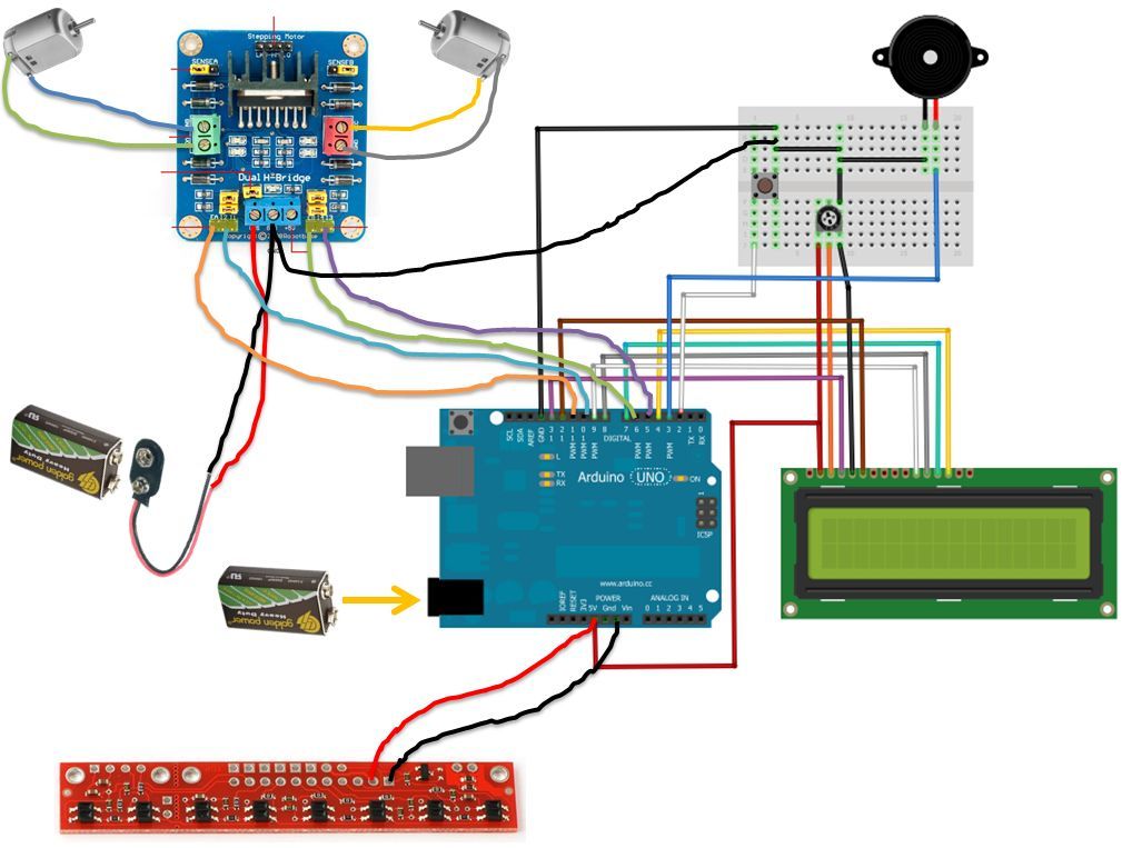
If the robot is positioned on the black line, it will continue moving forward. However, if it veers off the line and enters a white area, it will assess whether to correct its path to the left or right,...
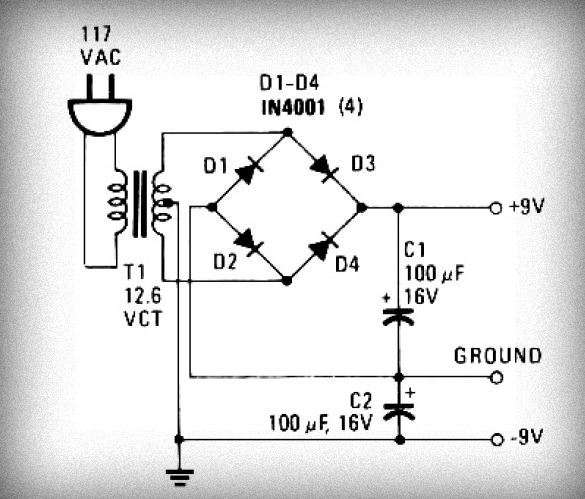
Initially, voltage from AC 220V or 110V enters the transformer, which reduces it to 12V AC. This AC voltage is then rectified using either four diodes or a bridge rectifier to convert it to DC voltage. The resulting DC...
A 0.1µF capacitor and a 500µF electrolytic capacitor were connected to both the transmitter and the receiver, but the system did not function as expected. Attempts to add diodes were also unsuccessful. Clarification is needed regarding the behavior of...
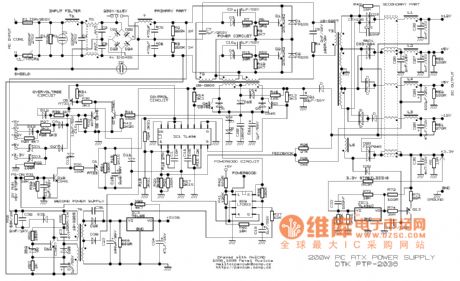
This example presents a switch DC regulated power supply circuit designed for buck-mode +5V applications. It consists of a power supply circuit, an impulsator, a voltage sampling or pulse width modulation circuit, and a buffering driver circuit, as illustrated...
This index is organized alphabetically by each word (excluding prepositions). For instance, the "Frost Alarm" will be listed under both "A" and "F". To efficiently locate a circuit, utilize the top index or employ your browser's search feature. In...