
Lvdt-driver-demodulator
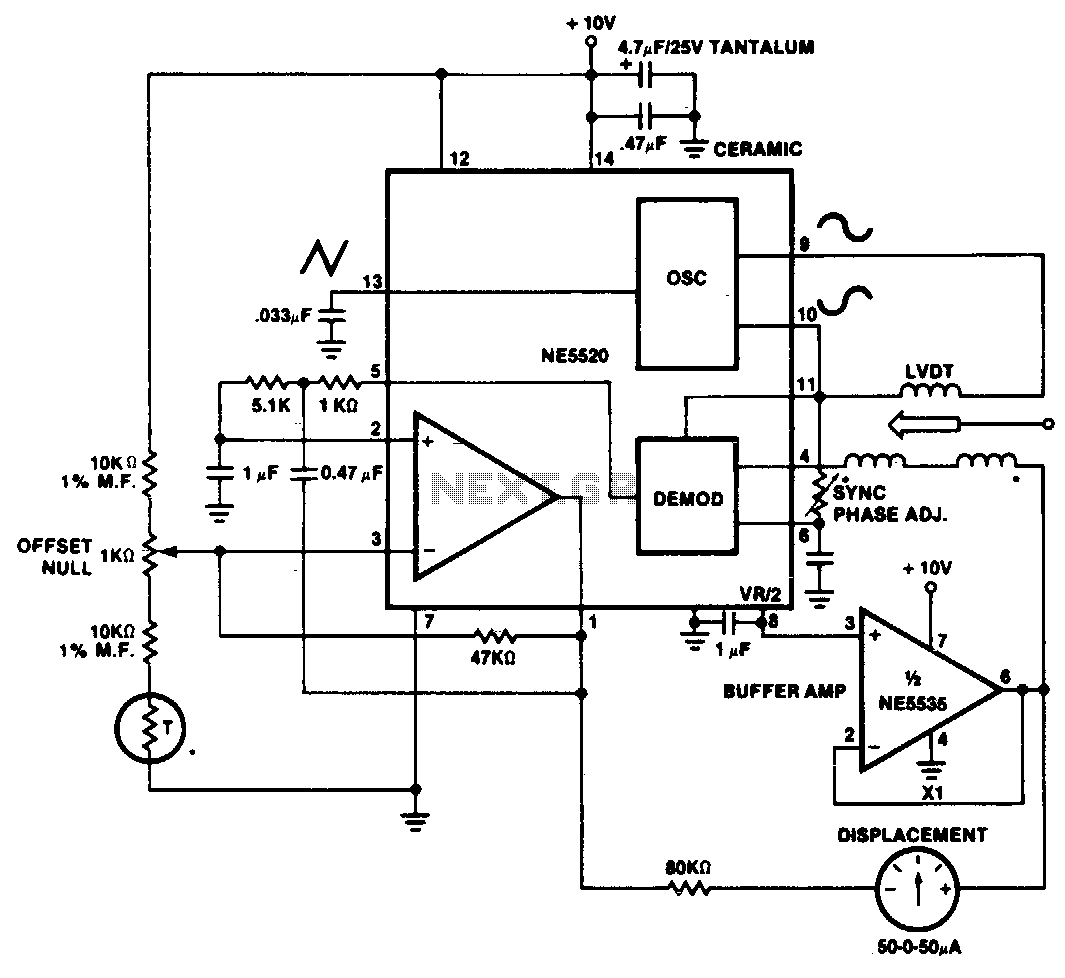
A simple motion transducer can be constructed using the provided circuit. The output is biased to one-half of the supply voltage, necessitating special interface circuitry for signal readout. One straightforward method involves utilizing a zero-center meter in a bridge configuration. Displacement can now be measured as either a positive or negative meter reading. The readout sensitivity is influenced by the specific LVDT and the gain of the error amplifier. Offsets can be nulled using a simple offset adjustment circuit as indicated.
The motion transducer circuit operates on the principle of linear variable differential transformer (LVDT) technology, which is commonly used for precise displacement measurements. In this configuration, the output voltage of the LVDT is centered around half the supply voltage, allowing for both positive and negative readings. This is particularly advantageous for applications that require bidirectional measurement.
To achieve accurate readings, a zero-center meter is employed in a bridge configuration. This setup effectively balances the circuit, allowing for a clear indication of displacement in both directions. The meter's sensitivity can be adjusted based on the characteristics of the LVDT and the gain settings of the error amplifier. The error amplifier plays a crucial role in amplifying the signal from the LVDT, ensuring that even small displacements can be detected and accurately represented on the meter.
Additionally, the circuit includes an offset adjustment feature, which is essential for eliminating any inherent offsets that may arise from component tolerances or environmental factors. This adjustment circuit allows the user to calibrate the system, ensuring that the readings reflect true displacement without any bias introduced by the circuitry itself.
Overall, this motion transducer circuit is an effective solution for applications requiring precise displacement measurement, providing clear and adjustable readouts while maintaining high sensitivity and accuracy.A very simple motion transducer can be constructed using the circuit shown. The output is biased to one-half the supply voltage. This requires special interface circuitry for the signal readout. One simple method is to use a zero center meter in a bridge configuration. Displacement now can be measured as a positive or negative meter reading. Readout sensitivity is a function of the particular LVDT and of the gain of the error amplifier. De offsets can be nulled by using a simple offset adjustment circuit as indicated. 🔗 External reference