
LX-800 Chaser & Strobe
The strobe controller functions as an integral component in lighting systems, particularly in theatrical and entertainment applications. Its design allows for seamless integration with a console PCB, ensuring that it can be operated remotely via a two-wire cable linked to the strobe head. The two-wire connection facilitates both power and control signals, allowing the strobe head to activate in sync with the audio or visual cues dictated by the console.
The operational control of the strobe controller is centralized on the console, where users can select input sources and manage output routing effectively. This centralized control enhances usability, enabling operators to adjust settings in real-time during performances. The input options for the strobe controller are versatile, accommodating either a bass-beat extractor circuit or a free-running oscillator. The bass-beat extractor is particularly useful in synchronizing the strobe effect with the rhythm of the music, creating a dynamic visual experience that enhances the overall ambiance of the performance. Conversely, the free-running oscillator provides a continuous strobe effect, independent of external audio, which can be employed for various artistic effects.
The shared use of the input circuits between the chaser and the strobe controller allows for a compact design, reducing the complexity and potential points of failure in the system. This feature also fosters flexibility in design, enabling the integration of additional features or modifications without extensive redesign of the existing circuitry.
In summary, the strobe controller is a pivotal element in lighting design, offering both reliability and versatility in theatrical applications. Its ability to connect directly to a console PCB and operate with various input sources makes it a valuable tool for lighting designers and operators alike.The strobe controller is essentially a stand-alone device, even though it is part of the console PCB. It connects through a two-wire cable to the remote strobe head. Control, input source selection and output routing are on the console. The input to the strobe controller and/or chaser is either through a bass-beat extractor circuit or a free-running oscillator, both of which are shared by the chaser and the strobe controller.
The chaser was developed out of an urgent need by one of the directors of a show I was involved in. It was designed, de-bugged and constructed in a single evening - because the director wouldn`t take no for an answer (show me a theatrical director wh 🔗 External reference
Related Circuits
Figure A illustrates the circuit of a direct-trigger timing light. The trigger voltage is obtained from the vehicle's ignition circuit via a direct connection to a spark plug. Figure B depicts a circuit utilizing an inductive pickup. A trigger...
This Adjustable Strobe Light is the bigger brother of the plain old strobe light. This one uses a much more powerful "horse shoe" Xenon tube which produces more light. You can also control the flash rate up to about...
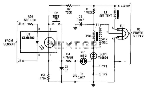
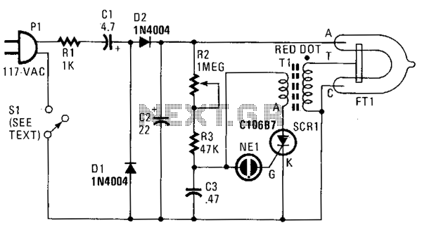
This strobe provides a visual indication of a sensor input. The input signal causes the light-dependent resistor (LDR) to change the charge across capacitors C1 and C3 through resistor R4. When NE1 fires, capacitor C3 discharges into SCR1, triggering...
The LM111 comparator can be utilized to design a relay driver with a TTL strobe, which enhances control over the relay driver. The strobe signal can be used to manage the relay operation more effectively. The LM111 is a high-speed...
In this strobe light, two circuits are required: one circuit charges a capacitor to create a 320 V DC potential between the cathode and anode of the flashtube, while the other circuit generates bursts of approximately 4000 V to...
Since the output buffer of P1 can sink 20mA (each output pin, but maximum IOL for all outputs was limited at 80mA), thus we can use P1 to drive LED display directly. As shown in the circuit, Two common-anode...
Warning: include(partials/cookie-banner.php): Failed to open stream: Permission denied in /var/www/html/nextgr/view-circuit.php on line 713
Warning: include(): Failed opening 'partials/cookie-banner.php' for inclusion (include_path='.:/usr/share/php') in /var/www/html/nextgr/view-circuit.php on line 713