Magnetic Amplifiers
1. Basic Principles and Operation
1.1 Basic Principles and Operation
Core Mechanism of Magnetic Amplifiers
A magnetic amplifier (mag amp) operates by exploiting the nonlinear B-H hysteresis characteristics of ferromagnetic materials. The device consists of a saturable reactor with at least two windings: a control winding (DC bias) and an AC winding (load current). The amplification effect arises from the controlled saturation of the core, which modulates the effective impedance of the AC winding.
Mathematical Derivation of Gain
The voltage-current relationship in the AC winding is governed by Faraday's law and the core's magnetic properties. For a sinusoidal input voltage VAC:
where NAC is the number of turns in the AC winding, and Φ is the magnetic flux. The core's permeability μ varies with the DC control current IDC:
where Isat is the saturation current. The effective inductance L of the AC winding is:
with Ac and lc being the core's cross-sectional area and magnetic path length, respectively. The gain G is derived from the ratio of output power (AC winding) to input power (control winding):
Key Operating Modes
- Unsaturated Mode: High impedance in AC winding, minimal load current
- Partially Saturated Mode: Linear amplification region
- Fully Saturated Mode: Low impedance, maximum load current
Practical Implementation Considerations
Core material selection critically impacts performance. Grain-oriented silicon steel offers high permeability and sharp saturation characteristics, while ferrites provide faster response times. Modern designs often incorporate feedback windings to improve linearity and reduce hysteresis losses. The typical frequency range spans 50 Hz to 20 kHz, with power handling from milliwatts to several kilowatts.
Historical Context and Modern Applications
First developed in the early 20th century, magnetic amplifiers saw extensive use in power regulation before being largely supplanted by semiconductor devices. Contemporary applications include:
- High-reliability aerospace power systems
- Nuclear reactor control circuits (radiation-hardened)
- Precision welding current regulation
The inherent galvanic isolation and overload tolerance make mag amps suitable for harsh environments where solid-state devices would fail. Recent advances in nanocrystalline alloys have revived interest in magnetic amplification for high-efficiency power conversion.
1.2 Core Materials and Their Properties
Magnetic Core Characteristics
The performance of a magnetic amplifier is critically dependent on the core material's magnetic properties. The most important parameters include:
- Saturation flux density (Bsat) - Maximum magnetic flux the material can sustain before saturation.
- Coercivity (Hc) - Resistance to demagnetization, affecting hysteresis losses.
- Permeability (μ) - Ratio of magnetic flux density to magnetic field intensity.
- Curie temperature (Tc) - Temperature at which the material loses ferromagnetism.
The relationship between flux density (B) and magnetic field intensity (H) is described by the hysteresis loop, which determines energy losses:
Common Core Materials
Silicon Steel (Electrical Steel)
Silicon steel, typically containing 3–5% silicon, is widely used due to its balanced properties:
- High saturation flux density (~2.0 T)
- Moderate permeability (μr ≈ 400–1500)
- Relatively low hysteresis losses
The addition of silicon increases resistivity, reducing eddy current losses. Grain-oriented silicon steel exhibits anisotropic properties, with superior performance along the rolling direction.
Nickel-Iron Alloys (Permalloy)
Nickel-iron alloys (e.g., 80% Ni, 20% Fe) offer extremely high permeability (μr up to 100,000) but lower saturation flux density (~0.8 T). These are used in:
- High-sensitivity applications
- Low-power magnetic amplifiers
- Precision current sensing
The permeability of permalloy is highly dependent on heat treatment and annealing processes.
Amorphous and Nanocrystalline Alloys
Modern amorphous metals (e.g., Metglas) and nanocrystalline materials provide:
- Very low hysteresis losses
- High resistivity (reducing eddy currents)
- Excellent frequency response up to 100 kHz
These materials are produced through rapid solidification techniques, resulting in a non-crystalline structure that minimizes domain wall pinning.
Core Losses and Frequency Dependence
Total core losses (Pcore) consist of hysteresis losses (Ph) and eddy current losses (Pe):
where:
- kh, ke are material constants
- f is the operating frequency
- B is the peak flux density
- α is the Steinmetz exponent (typically 1.6–2.1)
At higher frequencies (>10 kHz), eddy current losses dominate, making high-resistivity materials essential.
Practical Selection Criteria
When selecting core materials for magnetic amplifiers, engineers must consider:
- Operating frequency range - Higher frequencies require thinner laminations or amorphous materials.
- Power level - High-power applications need high Bsat materials.
- Temperature stability - Critical for aerospace and military applications.
- Cost constraints - Silicon steel offers the best cost-performance ratio for most industrial applications.
Recent advances in nanocrystalline materials have enabled magnetic amplifiers to operate at higher efficiencies and power densities, particularly in switched-mode power supplies and renewable energy systems.
1.3 Comparison with Electronic Amplifiers
Fundamental Operating Principles
Magnetic amplifiers (magamps) and electronic amplifiers (e.g., vacuum tubes, transistors) achieve signal amplification through fundamentally different mechanisms. Magamps rely on nonlinear inductance in saturable reactors, where a small DC control current modulates the core's permeability, altering the AC load current. In contrast, electronic amplifiers use active devices (transistors or tubes) to directly modulate electron flow via voltage or current inputs. The gain in magamps is derived from the ratio of load power to control power, whereas electronic amplifiers exhibit voltage/current gain defined by device parameters like transconductance (gm) or current gain (β).
Efficiency and Power Handling
Magamps excel in high-power applications (e.g., industrial control, aerospace) due to their absence of semiconductor junctions, enabling operation at kilowatt levels with minimal heat dissipation. Their efficiency (η) is governed by core losses (hysteresis, eddy currents) and can exceed 90% in optimized designs. Electronic amplifiers, particularly class-AB or class-D, achieve comparable efficiency only at lower frequencies and suffer from switching losses in high-power regimes. For instance, a magamp handling 10 kW at 400 Hz may exhibit η ≈ 92%, while a silicon IGBT-based amplifier at the same power typically reaches η ≈ 85%.
Frequency Response and Bandwidth
The bandwidth of magamps is intrinsically limited by the core's magnetic relaxation time (τ = L/R), restricting operation to sub-100 kHz frequencies. Electronic amplifiers, however, leverage fast carrier mobility (e.g., electron drift in semiconductors) to achieve gigahertz bandwidths. For example, a push-pull BJT amplifier can deliver flat response from DC to 100 MHz, while a magamp's response rolls off beyond 10 kHz due to core saturation dynamics:
Noise and Distortion Characteristics
Magamps exhibit lower thermal noise than electronic amplifiers, as they lack shot noise (from semiconductor junctions) and flicker noise. However, they introduce harmonic distortion from core hysteresis, quantified by the total harmonic distortion (THD) metric. A typical magamp may show THD < 2% at 60 Hz, while a low-noise op-amp (e.g., LT1028) achieves THD < 0.0003% at 1 kHz. The noise figure (NF) of magamps is dominated by Barkhausen noise from domain wall motion, whereas electronic amplifiers contend with Johnson-Nyquist noise.
Reliability and Environmental Robustness
The solid-state nature of magamps (no moving parts or fragile cathodes) grants them superior reliability in extreme environments. They are immune to ionizing radiation, EMP, and temperature extremes (−55°C to +200°C for ferrite cores), outperforming semiconductor amplifiers. Case studies in nuclear power control systems show magamp MTBF exceeding 500,000 hours, compared to 100,000 hours for radiation-hardened MOSFET amplifiers.
Modern Hybrid Architectures
Contemporary designs often combine magamps with electronic components to leverage both technologies. For instance, magamp-post-regulated switch-mode power supplies use a magamp for precise secondary-side voltage control, while MOSFETs handle high-frequency switching. This hybrid approach achieves efficiencies of 94% with ripple < 10 mV, as demonstrated in aerospace power systems like the Boeing 787's auxiliary power units.
2. Core Geometry and Windings
2.1 Core Geometry and Windings
The performance of a magnetic amplifier is critically dependent on the geometry of its core and the configuration of its windings. The core material, shape, and winding arrangement dictate the amplifier's saturation characteristics, efficiency, and frequency response.
Core Material and Geometry
The core of a magnetic amplifier is typically constructed from high-permeability, low-hysteresis materials such as grain-oriented silicon steel, nickel-iron alloys (e.g., Permalloy), or amorphous metallic glass. The core geometry influences the magnetic path length (lm) and cross-sectional area (Ac), which directly affect inductance and saturation behavior.
where:
- L is the inductance,
- N is the number of turns,
- μ0 is the permeability of free space,
- μr is the relative permeability of the core material,
- Ac is the cross-sectional area,
- lm is the magnetic path length.
Toroidal cores are often preferred due to their closed magnetic path, minimizing flux leakage and external interference. Laminated cores reduce eddy current losses, while tape-wound cores enhance high-frequency performance.
Winding Configurations
The windings in a magnetic amplifier consist of at least two coils: a control winding and an AC (load) winding. The control winding is driven by a DC or low-frequency signal, while the AC winding carries the amplified output. The turns ratio (Nc/Nac) determines the gain and coupling efficiency.
where dΦ/dt is the rate of change of magnetic flux, controlled by the saturation state of the core.
Bifilar winding techniques are sometimes employed to improve coupling and reduce parasitic capacitance. The winding resistance (Rw) and leakage inductance (Ll) must be minimized to prevent power losses and phase distortion.
Practical Considerations
In high-power applications, forced air or liquid cooling may be necessary to manage thermal losses. Core stacking and interleaved windings help distribute heat and reduce hotspots. The choice of insulation materials (e.g., Nomex, Mylar) is crucial for high-voltage isolation and thermal stability.
Modern magnetic amplifiers often use nanocrystalline cores for superior frequency response and reduced core losses. The geometry is optimized using finite element analysis (FEA) to balance magnetic efficiency, thermal performance, and physical size constraints.
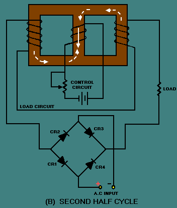
Control and Load Circuits
Control Circuit Operation
The control circuit in a magnetic amplifier regulates the output by varying the DC bias current in the control winding. The core's saturation level is modulated by the control current, which adjusts the effective impedance of the load winding. The relationship between control current \( I_c \) and load current \( I_L \) is nonlinear due to the B-H hysteresis characteristics of the core material. For small-signal analysis, the incremental gain \( G \) is derived from the slope of the transfer curve:
where \( N_c \) and \( N_L \) are the turns of the control and load windings, \( \mu_r \) is the relative permeability, \( A_e \) is the effective cross-sectional area, and \( l_e \) is the magnetic path length. The control circuit's time constant \( \tau_c \) is dominated by the inductance \( L_c \) and resistance \( R_c \):
Load Circuit Dynamics
The load circuit typically includes an AC supply and a rectifier (for DC applications). The load current \( I_L \) is constrained by the core's saturation flux density \( B_{sat} \):
In practical designs, a feedback winding is often added to linearize the response. The feedback factor \( \beta \) is defined as:
where \( N_f \) is the feedback winding turns and \( \Phi \) is the magnetic flux. This introduces a closed-loop gain \( G_{cl} \):
Harmonic Distortion and Compensation
Nonlinearity in the B-H curve introduces harmonic distortion, quantified by the total harmonic distortion (THD):
where \( I_n \) is the nth harmonic component. To mitigate THD, push-pull configurations or predistortion networks are employed. The latter uses a nonlinear impedance \( Z_p \) in series with the control winding to cancel core nonlinearities.
Practical Implementation
In high-power applications, thyristor-driven control circuits are common. The gate trigger angle \( \alpha \) directly influences the effective control current:
This method enables phase-controlled amplification, useful in motor drives and power regulation. Core materials like grain-oriented silicon steel or amorphous alloys are selected for their square B-H loops and low core losses.
2.3 Feedback Mechanisms
Feedback in magnetic amplifiers enhances stability, linearity, and gain control by reintroducing a portion of the output signal into the input circuit. The core principle relies on the nonlinear magnetic properties of saturable reactors, where feedback modifies the effective permeability and thus the amplification characteristics.
Negative Feedback in Magnetic Amplifiers
Negative feedback reduces gain but improves bandwidth and distortion. The feedback signal opposes the input, stabilizing the amplifier against parameter variations. For a magnetic amplifier with gain A and feedback factor β, the closed-loop gain Af is:
In practical implementations, negative feedback is achieved by winding a feedback coil on the same core as the control winding. The current in this coil generates a magnetic flux that opposes the control flux, effectively linearizing the B-H curve operation region.
Positive Feedback and Regeneration
Positive feedback increases gain and sensitivity at the cost of stability. This technique was historically used in magnetic amplifier designs for bistable operation or high-gain applications. The closed-loop gain with positive feedback becomes:
When Aβ approaches unity, the system becomes highly sensitive to input variations, useful in switching applications. However, careful design is required to prevent unwanted oscillations.
Feedback Implementation Techniques
Three primary methods exist for implementing feedback in magnetic amplifiers:
- Current feedback: A portion of the output current is fed back via a separate winding.
- Voltage feedback: The output voltage is sampled and fed back through a resistive divider.
- Flux feedback: Direct magnetic coupling between output and input windings.
The choice depends on whether current, voltage, or power amplification is the primary objective. Flux feedback provides the fastest response but requires precise winding alignment.
Mathematical Analysis of Feedback Effects
The incremental gain of a magnetic amplifier with feedback can be derived from the core's magnetization curve. Let μΔ represent the incremental permeability:
With feedback, the effective permeability μeff becomes:
where N is the number of turns and l the magnetic path length. The ± sign corresponds to negative/positive feedback respectively.
Practical Considerations
In power applications, feedback windings must handle significant currents without excessive heating. Litz wire is often used to minimize skin effect losses at higher frequencies. The feedback ratio must be carefully balanced against:
- Core saturation characteristics
- Load impedance variations
- Temperature effects on magnetic properties
Modern implementations often combine magnetic amplifiers with semiconductor devices for improved feedback precision, using op-amps or digital controllers to maintain optimal operating points across varying conditions.
3. Industrial Control Systems
3.1 Industrial Control Systems
Magnetic amplifiers (magamps) have been historically significant in industrial control due to their ruggedness, reliability, and ability to handle high power levels without semiconductor components. Their operation relies on the nonlinear B-H curve of saturable reactors, enabling amplification through controlled saturation of magnetic cores.
Core Operating Principle
The gain of a magnetic amplifier is governed by the saturation characteristics of its ferromagnetic core. The control winding (input) and load winding (output) share a common magnetic path. When the control current drives the core into saturation, the impedance of the load winding drops sharply, allowing larger currents to flow.
where G is the gain, Nc and Nl are turns of control and load windings, and μsat, μunsat are permeabilities in saturated/unsaturated states.
Feedback Stabilization
Industrial magamps often employ self-saturating circuits with rectifier feedback to improve response time and linearity. A typical configuration uses:
- DC control signals (0–10V or 4–20mA standard)
- Carrier frequencies between 50Hz–400Hz
- Phase-controlled AC output via gate windings
Modern Applications
While largely replaced by solid-state devices, magamps persist in:
- High-temperature environments (e.g., furnace controls)
- Nuclear power systems (radiation-hardened operation)
- High-voltage DC transmission (HVDC valve controls)
Case Study: Steel Mill Current Regulation
A 1980s-era rolling mill employed a 3-stage magamp system to regulate 1500A DC motor currents. The design achieved ±0.5% stability through:
where τ is the time constant, Lcore is unsaturated inductance, and Rload is motor resistance.
Advantages Over Semiconductor Drives
| Parameter | Magnetic Amplifier | Thyristor Drive |
|---|---|---|
| Overload Capacity | 500% for 1s | 150% for 1s |
| MTBF | >100,000 hrs | 50,000 hrs |
| EMI Susceptibility | Immune | Requires filtering |
3.2 Power Regulation and Conversion
Magnetic amplifiers excel in power regulation due to their inherent nonlinear saturation characteristics. The core's hysteresis loop enables precise control of output power by modulating the DC bias current in the control winding. The relationship between input and output power is governed by the amplifier's gain, which depends on the core material's permeability and the winding configuration.
Core Saturation Dynamics
The power transfer efficiency of a magnetic amplifier is maximized when the core operates near saturation. The critical parameter is the saturation flux density (Bsat), which determines the maximum power handling capability. The output voltage regulation follows:
where Nload and Ncontrol are the turns ratios, and dΦ/dt is the rate of change of magnetic flux. The flux density B relates to the applied magnetic field H through the material's hysteresis curve.
Feedback Control for Regulation
Closed-loop regulation is achieved by sampling the output voltage and feeding it back to the control winding. A proportional-integral (PI) controller adjusts the DC bias to maintain stable output under load variations. The transfer function of the regulated system is:
where Kp is the proportional gain, Ti the integral time constant, and τ the core's effective time delay.
Practical Implementation
In three-phase power systems, magnetic amplifiers are often configured in a delta arrangement to handle higher currents. The following diagram illustrates a typical three-phase magnetic amplifier regulator:
Key design considerations include:
- Core material selection: Grain-oriented silicon steel or amorphous metal alloys for high permeability and low losses.
- Thermal management: Forced air cooling or heat sinks to dissipate core hysteresis and winding losses.
- Harmonic suppression: LC filters to mitigate distortion from nonlinear saturation effects.
Comparison with Semiconductor Alternatives
While modern switching regulators offer higher efficiency, magnetic amplifiers remain preferred in:
- High-reliability aerospace power systems (immune to radiation effects)
- Industrial welders and induction heaters (handling multi-kW loads)
- Nuclear power plant instrumentation (intrinsic galvanic isolation)
The table below quantifies key performance metrics:
| Parameter | Magnetic Amplifier | Switching Regulator |
|---|---|---|
| Efficiency | 85-92% | 93-98% |
| Transient Response | 10-100 ms | 1-10 μs |
| MTBF | >500,000 hrs | 100,000 hrs |
3.3 Military and Aerospace Uses
Reliability in Harsh Environments
Magnetic amplifiers (magamps) are favored in military and aerospace applications due to their inherent ruggedness and immunity to extreme conditions. Unlike semiconductor-based amplifiers, magamps exhibit no performance degradation under high radiation, extreme temperatures, or electromagnetic interference (EMI). Their core saturation principle ensures stable operation even in the presence of ionizing radiation, making them indispensable in satellite and spacecraft power systems.
Power Regulation in Defense Systems
In military radar and communication systems, magamps serve as high-power regulators due to their ability to handle kilowatt-level signals without semiconductor switching losses. The absence of solid-state components eliminates thermal runaway risks in high-duty-cycle applications. For instance, the AN/SPY-1 radar system employs magamps for stable power delivery in phased-array antennas, where precise amplitude control is critical.
Here, B is magnetic flux density, H is magnetic field strength, and lc is core path length. This equation governs the dynamic response of saturable reactors in magamps, enabling precise control of power delivery.
Aerospace Voltage Stabilization
Magamps stabilize bus voltages in aircraft and spacecraft by compensating for load variations without introducing switching noise. The Boeing 787 Dreamliner’s auxiliary power unit (APU) uses magamps to condition 270V DC power, leveraging their fault tolerance—a single magamp failure doesn’t cascade into system-wide collapse, unlike MOSFET-based converters.
Nuclear and EMP Hardening
Strategic defense systems prioritize magamps for electromagnetic pulse (EMP) hardening. When exposed to EMPs, semiconductor devices experience latch-up or gate oxide rupture, whereas magamps remain operational. The U.S. Minuteman III ICBM guidance system historically used magamps in its analog flight computers for this reason, achieving nanosecond-scale response times without vulnerability to transient radiation effects.
Case Study: Satellite Attitude Control
NASA’s Voyager probes utilized magamps in their thruster control systems. The non-linear gain characteristic:
where Ns and Nc are secondary and control winding turns, allowed precise torque adjustment via magnetic bias currents, eliminating the need for failure-prone mechanical potentiometers in deep-space conditions.
4. Reliability and Durability
4.1 Reliability and Durability
Core Mechanisms Influencing Reliability
Magnetic amplifiers rely on the nonlinear magnetic properties of saturable cores, typically made of grain-oriented silicon steel or nickel-iron alloys. The primary failure modes stem from core hysteresis losses, winding insulation breakdown, and thermal degradation. The reliability is quantified by the mean time between failures (MTBF), which can be derived from the Arrhenius equation for thermal aging:
where A is a material-specific constant, Ea is the activation energy, k is Boltzmann’s constant, and T is the absolute temperature.
Thermal Management and Derating
Excessive heat accelerates insulation aging and core losses. The permissible temperature rise (ΔT) is governed by the thermal resistance (Rth) of the magnetic amplifier assembly:
where Ploss includes eddy current and hysteresis losses. Derating curves, typically provided by manufacturers, specify the allowable load current reduction at elevated ambient temperatures.
Mechanical Stress and Vibration Resistance
In aerospace and industrial applications, mechanical vibration can lead to winding fatigue or core delamination. The natural frequency (fn) of the assembly must avoid resonance with external vibrations:
where k is the stiffness of the mounting structure and m is the mass of the core and windings. Damping materials like silicone potting compounds are often used to mitigate high-frequency oscillations.
Case Study: Military-Grade Magnetic Amplifiers
U.S. military specifications (e.g., MIL-STD-810) require magnetic amplifiers to endure:
- Temperature cycling (−55°C to +125°C)
- Humidity exposure (95% RH at 40°C)
- Random vibration (14.1 Grms, 20–2000 Hz)
Data from field deployments show that properly potted units achieve MTBF values exceeding 100,000 hours under these conditions.
Material Selection for Longevity
The choice of core material directly impacts durability:
- Silicon steel: Low cost but prone to aging at high flux densities.
- Nanocrystalline alloys: Superior permeability and reduced losses, but sensitive to mechanical stress.
- Amorphous metals: Excellent high-frequency performance but brittle under thermal shock.
Accelerated Life Testing (ALT)
ALT protocols apply elevated stress levels (temperature, voltage, vibration) to predict failure rates. The Eyring model is commonly used for combined thermal-electrical stresses:
where L is the lifetime, V is the applied voltage, T is temperature, and m, B are empirical constants.
4.2 Efficiency and Performance Trade-offs
The efficiency of a magnetic amplifier is fundamentally governed by core losses, winding resistance, and control circuit dynamics. Unlike semiconductor amplifiers, where switching losses dominate, magnetic amplifiers exhibit hysteresis and eddy current losses that scale nonlinearly with frequency and flux density. The total power dissipation Ploss can be decomposed into:
Core Losses and Hysteresis Trade-offs
Hysteresis loss, derived from the area of the B-H loop, follows Steinmetz's empirical relation:
where kh is the material constant, f is frequency, Bm is peak flux density, and n (typically 1.6–2.1) depends on core material. High-permeability cores like nanocrystalline alloys reduce kh but may saturate at lower control currents, limiting gain.
Eddy Current Losses and Frequency Dependence
Eddy currents, induced by time-varying flux, are minimized by laminating the core or using powdered materials. The loss is approximated by:
Here, t is lamination thickness and ρ is resistivity. For high-frequency designs (e.g., >10 kHz), ferrite cores become essential despite their lower saturation flux density.
Copper Losses and Winding Optimization
Resistive losses in windings follow Pcopper = I2Rac, where Rac accounts for skin and proximity effects. Litz wire or foil windings mitigate this at high frequencies, but increase parasitic capacitance, introducing a trade-off between efficiency and bandwidth.
Efficiency vs. Linearity
Magnetic amplifiers achieve high efficiency (>90%) in saturation mode, but linear operation (for low-distortion applications) forces operation below saturation, increasing core losses. The linearity-efficiency product η·THD is a key figure of merit, often optimized via feedback control or pre-biasing techniques.
Thermal Management Implications
Core losses manifest as heat, requiring derating above 80–100°C. Forced air cooling or liquid cooling may be necessary in high-power designs (>1 kW), adding volume and cost. Thermal resistance models must account for core-winding thermal coupling, as hotspots degrade insulation over time.
Practical designs balance these factors through iterative simulation and material selection, often leveraging finite-element analysis (FEA) tools for loss modeling. Military and aerospace applications, where reliability trumps efficiency, may prioritize derated operation, while industrial drives push efficiency boundaries with advanced core materials like Metglas.
4.3 Modern Alternatives and Obsolescence
Magnetic amplifiers, once prominent in early-to-mid 20th-century power control and signal processing, have largely been supplanted by semiconductor-based alternatives. The transition was driven by semiconductor devices offering superior efficiency, faster response times, and compact form factors. The primary competitors include silicon-controlled rectifiers (SCRs), insulated-gate bipolar transistors (IGBTs), and power MOSFETs.
Semiconductor-Based Replacements
The displacement of magnetic amplifiers by solid-state devices can be attributed to several key advantages:
- Higher Switching Speeds: Semiconductor devices operate at microsecond or nanosecond timescales, whereas magnetic amplifiers are limited by core saturation dynamics, typically in the millisecond range.
- Improved Efficiency: Solid-state amplifiers exhibit lower conduction and switching losses, reducing heat dissipation.
- Miniaturization: Integrated circuits enable compact designs, unlike the bulky magnetic cores and windings required for saturable reactors.
The gain of a semiconductor amplifier, such as a MOSFET, is governed by its transconductance (gm):
where ID is the drain current and VGS is the gate-source voltage. This parameter is orders of magnitude higher than the effective gain achievable in magnetic amplifiers.
Niche Applications of Magnetic Amplifiers
Despite obsolescence in mainstream electronics, magnetic amplifiers persist in specialized scenarios:
- High-Reliability Systems: Aerospace and military applications exploit their resilience to electromagnetic pulses (EMPs) and radiation.
- High-Temperature Environments: Unlike semiconductors, magnetic cores do not suffer from thermal runaway.
- Retro-Technology Maintenance: Legacy industrial systems still in operation may require magnetic amplifier servicing.
Comparative Analysis: Magnetic vs. Solid-State Amplifiers
The following table summarizes key differences:
| Parameter | Magnetic Amplifier | Solid-State Amplifier |
|---|---|---|
| Bandwidth | ~kHz | ~MHz-GHz |
| Efficiency | 70-85% | 90-98% |
| Size/Weight | Bulky | Compact |
| Failure Mode | Graceful degradation | Catastrophic |
Future Prospects
Research into advanced magnetic materials, such as metallic glasses and nanocrystalline cores, aims to revive interest in magnetic amplifiers for ultra-high-reliability applications. However, the dominance of semiconductor technology in power electronics remains unchallenged due to continuous advancements in wide-bandgap materials like silicon carbide (SiC) and gallium nitride (GaN).
where Ron represents the on-resistance of a power MOSFET, a critical factor in minimizing conduction losses. Modern SiC devices achieve Ron values below 10 mΩ, further marginalizing magnetic solutions.
5. Key Research Papers
5.1 Key Research Papers
- A 10.3GS/s 6bit (5.1 ENOB at Nyquist) time-interleaved/pipelined ADC ... — A 10.3GS/s ADC with 5GHz input BW and 6 bit resolution in 90nm CMOS is presented. The architecture is based on an 8 way interleaved/ pipelined ADC using open-loop amplifiers and digital calibration. The measured performance is 5.8 ENOB (36.6dB SNDR) for a 100MHz input signal and 5.1 ENOB (32.4dB SNDR) for a 5GHz input (Nyquist) with phase offset correction across the interleaved array.
- PDF Magnetic Amplifiers for Voltage Regulation Applications — Abstract The purpose of this thesis is to present research on magnetic amplifiers and to discuss how magnetic amplifiers are useful in voltage regulation applications. Beginning with a background in magnetics and magnetic properties, this thesis outlines the importance of the B-H curve and
- Calculation and validation of stray-field loss in magnetic and non ... — Accurate computation of stray-field loss in numerical simulation depends on reliable magnetic properties and appropriate loss model [11, 12]. Different loss modelling methods are presented and developed continuously to investigate loss characteristics of magnetic materials under sinusoidal and non-sinusoidal excitations [13 - 16].
- PDF On Magnetic Amplifiers in Aircraft Applications — The frequency of the generator offered the perfect conditions for a magamp controller. A key parameter in designing magnetic amplifiers (magamps) is low losses. New amorphous alloys offer new possibilities of the technique in designing magnetic amplifiers, because of their extremely low losses.
- PDF Dan 1 Cew - Virginia Tech — Recently, models of the small-signal control loop behavior of the magnetic amplifier have been developed [1-7]. These models provide a basis for stabi- lizing the control loop and designing control circuitry for enhanced perform- ance. Use of these models and typical magnetic amplifier regulation has been limited to single-loop voltage-mode ...
- PDF Efficient and Wideband Load Modulated Power Amplifiers for Wireless ... — The content of the following papers partially overlaps with the appended papers or is out of the scope of this thesis. [a] E. Liu* H. Zhou*, C. Fager, and H Wang, "A 25 − 40 GHz Three Way Power Amplifier with No Main PA Load Modulation Achieving Broadband DeepPowerBack-OffEກ킨ciencyEnhancement,"submittedto IEEE International Solid ...
- Development of a Transient Magnetic Field Sensor Based on Digital ... — Transient magnetic field sensors are used in various electromagnetic environment measurement scenarios. In this paper, a novel magnetic field sensor based on a digital integrator was developed. The antenna was a small B-DOT loop. It was designed optimally ...
- A Wireless Power Pickup Based on Directional Tuning Control of Magnetic ... — This paper proposes a novel inductor-capacitorinductor wireless power pickup with directional tuning control (DTC) for a magnetic amplifier. The proposed technique allows the power pickup to achieve full-range tuning/detuning operation to regulate power flow and maintain the output voltage to be constant.
5.2 Recommended Books
- TRANSFORMERS AND INDUCTORS FOR POWER ELECTRONICS - Wiley Online Library — 1.6 Magnetic Materials for Power Electronics 16 1.6.1 Soft Magnetic Materials 17 1.6.2 The Properties of some Magnetic Materials 19 1.7 Problems 21 References 21 Further Reading 21 SECTION I INDUCTORS 23 Chapter 2 Inductance 25 2.1 Magnetic Circuits 25 2.2 Self and Mutual Inductance 30 2.3 Energy Stored in the Magnetic Field of an Inductor 34
- PDF OPERATIONAL AMPLIFIERS: Theory and Practice - MIT OpenCourseWare — 6.2.3 A Magnetic-Suspension System 214 6.3 Describing Functions 217 6.3.1 The Derivation of the Describing Function 217 6.3.2 Stability Analysis with the Aid of Describing Func-tions 226 6.3.3 Examples 231 6.3.4 Conditional Stability 234 6.3.5 Nonlinear Compensation 240 Problems 242 VII DIRECT-COUPLED AMPLIFIERS 249
- Electromagnetics and Transmission Lines: Essentials for Electrical ... — E-Book. 978-1-119-88192-6. October 2022. $$102.00. Hardcover. 978-1-119-88190-2. November 2022. $$127.95. Description. Electromagnetics and Transmission Lines. Textbook resource covering static electric and magnetic fields, dynamic electromagnetic fields, transmission lines, antennas, and signal integrity within a single course ...
- PDF Power Amplifiers - Learn About Electronics — Power Amplifiers Introduction to Power Amplifiers Power Amplifiers • Crossover distortion. Amplifier circuits form the basis of most electronic systems, many of which need to produce high power to drive some output device. Audio amplifier output power may be a nything from less than 1 Watt to several hundred Watts. Radio frequency amplifiers
- PDF OPERATIONAL AMPLIFIERS: Basic Circuits and Applications - Texas A&M ... — Op Amp Powering Op Amp Powering: • 0.1 mF capacitance: 1) Prevents the AC noise coming from non-zero impedance between the supply and the ground. 2) Neutralizes spurious feedback loops arising from non-zero Impedance between the supply and ground. • 10 mF capacitance provides board-level by pass. • Using wide ground traces is recommended ...
- (PDF) Advanced Practical Electronics - Circuits & Systems - ResearchGate — The first chapter is Introduction to Electronic Systems; Chapter 2 is on Power Supplies (using linear 7 switching regulators); Chapter 3 is on Power Devices; Chapter 4 is on the Theory of ...
- Differential amplifiers - Book chapter - IOPscience — Figure 5.2 shows the current distribution in the two branches, and the dashed/solid curve represents the current in the left/right branch, respectively. The horizontal axis is the difference between the two input voltages, which is also called the differential input: .It can be verified easily: the sum of these two currents is always equal to the bias current, .
- PDF Electromagnetics and Applications - MIT OpenCourseWare — Electromagnetics and Applications - MIT OpenCourseWare ... Preface - ix -
5.3 Online Resources
- Textbook contents | Electromagnetic Field Theory: A Problem Solving ... — Textbook contents: Front-End Matter, Chapter 1: Review of Vector Analysis, Chapter 2: The Electric Field, Chapter 3: Polarization and Conduction, Chapter 4: Electric Field Boundary Value Problems, Chapter 5: The Magnetic Field, Chapter 6: Electromagnetic Induction, Chapter 7: Electrodynamics-Fields and Waves, Chapter 8: Guided Electromagnetic Waves, and Chapter 9: Radiation.
- Microelectronic Circuits 8e Instructor Resources - Oxford Learning Link — A word from the authors about this important revision This site is contains all of the instructor resources that accompany Microelectronic Circuits, Eighth Edition: • An electronic version of the Instructor's Solutions Manual. Written by Adel Sedra, the Manual contains detailed solutions to all chapter exercises and end-of-chapter problems.
- PDF Lab 4 Instrumentation Amplifier 3.4 - University of California, Berkeley — Lab Objectives In the previous lab, we learned about operational amplifiers and how to implement basic configurations such as the amplifiers, Schmitt triggers, and comparators. Now that you are familiar with operational amplifiers, we will build a sensor interface which is one of the most common applications of operational amplifiers.
- PDF ELE531: Electromagnetics Course Outline (F2024) — Student Life and Learning Support offers group-based and individual help with writing, math, study skills, and transition support, as well as resources and checklists to support students as online learners.
- PDF 6.013 Electromagnetics and Applications, Course Notes — The main objectives of the text are to: 1) convey those big ideas essential to understanding the electromagnetic aspects of modern electrical and computer systems, 2) expose students to enough examples to make the big ideas tangible and erase most naiveté about dominant applications, 3) provide computational experience with Maxwell's equations sufficient to treat the basic examples, 4 ...
- PDF Electronic Feedback Systems: Front Material - MIT OpenCourseWare — Chapters 2 to 6 and Chapter 13 present the techniques necessary to model, analyze, and design electronic feedback systems. As with the circuit-related material, the detail is greater than the minimum necessary for a background in the design of connections that use operational amplifiers.
- Microelectronic Circuits 8e Student Resources - Oxford Learning Link — This should allow you to get started doing simulations of your own. Data Sheets Circuit components and devices—such as diodes, amplifiers, and BJTs—all have different specifications when manufactured by different companies. These specifications are listed on data sheets.
- PDF Material property data for engineering materials - Ansys — Document Information This white paper is part of a set of teaching resources to help introduce students to materials, processes and rational selecions.