Magnetic-Radiation Remote-Controls

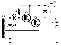
This unit serves as a short-range, single-channel remote control. When the pushbutton on the transmitter circuit is briefly activated, the LED D1 in the receiver illuminates, and an optional beeper or relay can be triggered. The circuit operates on a non-modulated 35 kHz frequency carrier transmitter and features a high-gain two-stage 35 kHz amplifier receiver, followed by a frequency-voltage converter and DC load driver. No external antenna is necessary for either the transmitter or receiver due to the low frequency operation. The antennas consist of 10 mm diameter, 10 cm long ferrite rods supporting the coils. The receiver functions at an ultra-low voltage supply (3V) and has a standing current of 100 µA, allowing it to remain in standby mode for years before requiring a battery replacement. Limitations include short-range operation (approximately covering a medium-sized apartment), a high number of windings for the coils, and significant current draw by the transmitter. However, the latter issue is mitigated by the fact that only a brief pulse from the transmitter is needed to activate the receiver, meaning the transmitter's battery should last a long time if not operated continuously. Q1 and Q2 are configured as a Darlington pair to maximize output from a Hartley type oscillator. C2 must be adjusted to achieve the highest sinewave output, which is best observed on an oscilloscope. In the prototype, the sinewave amplitude measured at C1 leads reached 800V peak-to-peak at a 9V supply and 450 mA current. Q1 and Q2 form a two-stage linear amplifier, amplifying the small 35 kHz signal picked up by L1, which then feeds Q3 configured as a pulse-to-DC converter. When the input signal reaches Q3, the collector voltage of this transistor drops, activating LED D1 (or the optional beeper or relay) through Q4. For shorter range operation, Q2 in the transmitter can be omitted, connecting the emitter of Q1 to the tap of the L1 coil. In this configuration, the circuit can be powered by a 9V PP3 alkaline battery, drawing approximately 100 mA of current. The receiver must be tuned to the transmitter frequency, starting with a 470 pF value for C1, and adjusting it with small capacitors in parallel to achieve the highest AC voltage output at the collector of Q2 or Q1, ideally measured with an oscilloscope. The value of C1 may range from about 400 to 800 pF. During setup, it is advisable to temporarily connect the transmitter to a 6 or 9V regulated power supply to conserve battery life. A small DIL 5V reed relay was utilized despite the 3V supply of the receiver. Testing indicated that these relays activate with a coil voltage in the range of 1.9 to 2.1V, with coil resistances varying from 140 to 250 Ohms.
The schematic for this remote control circuit incorporates several key components and configurations to achieve efficient operation. The transmitter section features a Hartley oscillator, formed by Q1 and Q2 in a Darlington pair configuration, which enhances the output signal. The oscillator generates a 35 kHz carrier frequency, which is transmitted via the ferrite rod antenna. The receiver section is designed to detect this frequency using an L1 coil, which is tuned to resonate at the same frequency as the transmitter.
The tuning process involves adjusting C1, which is critical for maximizing the signal amplitude received. This adjustment is performed while the transmitter is activated, ensuring that the receiver is optimally configured for the specific distance and environmental factors present. The use of a pulse-to-DC converter (Q3) allows for the conversion of the received AC signal into a usable DC signal to drive the output devices, such as an LED, beeper, or relay.
The overall design emphasizes low power consumption, allowing the receiver to operate efficiently on a minimal 3V supply with a low standing current. This is particularly advantageous for applications requiring long-term operation without frequent battery changes. The use of a reed relay, which activates at lower voltages, complements the low power design and provides a reliable switching mechanism for various output applications.
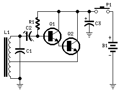
In conclusion, this remote control circuit is an effective solution for short-range wireless communication, utilizing a simple yet effective design that balances performance and power efficiency. The careful selection of components and tuning methods ensures reliable operation in various scenarios, making it suitable for a range of remote control applications.This unit can be useful as a short-range, single-channel remote-control. When the pushbutton in the transmitter circuit is briefly activated, the LED D1 in the receiver illuminates and an optional beeper or relay can be operated. Circuit operation is based on a non-modulated 35KHz frequency carrier transmitter, and on a high-gain two-stage 35KHz a
mplifier receiver, followed by a frequency-voltage converter and DC load driver. No outer antenna is required on both transmitter and receiver sections, due to the very low frequency operation. The antennas are 10mm. diameter, 10cm. long ferrite rods supporting the coils. The receiver operates at ultra-low voltage supply (3V) and standing current (100 µA): in this manner it can be left in stand-by mode for years before a battery replacement is needed.
Snags are: the short-range operation (about a medium-sized apartment), the high number of windings for the coils and the high current drawn by the transmitter. Luckily, this latter snag is compensated by the fact that only a short pulse from the transmitter is needed to operate the receiver.
Therefore, if the transmitter is not operated continuously, its battery should last long. Q1 and Q2 are wired as a Darlington pair to obtain the highest possible output from a Hartley type oscillator. C2 must be trimmed to obtain the highest sinewave output (best viewed on oscilloscope). In the prototype the sinewave amplitude measured at C1 leads reached 800V peak-to-peak at 9V supply and 450mA current.
Q1 and Q2 form a two-stage linear amplifier. Therefore, the small 35KHz signal picked-up by L1 is highly amplified by these devices and feds Q3 wired as a pulse-to-DC converter. When the input signal reaches Q3, the collector voltage of this transistor goes low, thus activating the LED D1 (or the optional beeper or relay) by means of Q4.
Needing a shorter range operation, Q2 in the transmitter can be omitted. Therefore, the emitter of Q1 will be connected to the tap of L1 coil. In this case the circuit could be powered by a 9V PP3 alkaline battery, drawing about 100mA current. The receiver must be tuned to the transmitter frequency. Starting with a 470pF value for C1, you should try to modify its value by means of small capacitors wired in parallel to it, in order to obtain the highest AC voltage output at Q2 or Q1 collector (best measured with an oscilloscope). C1 value might vary from about 400 to 800pF. Do this setup with transmitter placed 4-5 meters away from receiver. During setup it is wise to temporarily connect the transmitter to a 6 or 9V regulated power supply, in order to save batteries.
A small DIL 5V reed-relay was used in spite of the 3V supply of the receiver. Several devices of this type were tested and it was found that they switch-on with a coil voltage value comprised in the 1. 9 - 2. 1V range. The coil resistance values varied from 140 to 250 Ohm. 🔗 External reference
