
magnetics application schematics
This measurement circuit is designed to accurately detect and measure magnetic fields and changes in position using advanced sensor technology. The calibration process is crucial for ensuring the accuracy of the measurements, particularly when environmental factors may alter the sensor's position relative to the conductor. The dual capability of measuring both DC and AC currents broadens the application potential of this circuit, making it suitable for various electronic devices.
The choice of operational amplifiers and MOSFETs plays a significant role in the performance and efficiency of the circuit. It is essential to select components that are compatible with low voltage operations, as this is critical for battery-powered applications. The recommendation for MOSFETs with low on-resistance (Rds(on)) ensures minimal power loss and heat generation during operation, which is vital for maintaining the longevity of portable devices.
Furthermore, the integration of a high-resolution ADC enhances the circuit's ability to detect minute changes in magnetic fields, which is essential for applications such as metal detection. The firmware's capability to handle slow drifts while responding to sudden changes ensures reliable operation in dynamic environments.
The design considerations regarding the placement of the HMC1052 sensor highlight the importance of minimizing interference from nearby components, particularly those that may generate magnetic fields. This attention to detail is crucial for achieving the desired accuracy and performance of the circuit.
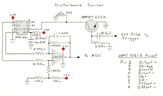
Overall, this circuit represents a sophisticated approach to magnetic field measurement and position detection, incorporating best practices in electronic design to ensure reliability and effectiveness in practical applications.Calibrate the measurement circuit by forcing a known conductor current and measuring the resulting voltage output. If sensor to conductor displacement changes, recalibrate This sensor circuit can measure DC and AC currents to the bandwidth of the op-amp.
Additional bandwidth limitation can be had by placing capacitance across the 475k-ohm feedback resistor. Other power supplies can be used with this circuit if the selected op-amp can operate. Note that the 1N4148 diode can be removed if reverse polarity protection is un-needed. Simple circuit for laptop computers, portable devices, etc. for detecting change in location (i. e. rotational movement). The HMC1021S is placed on a horizontal circuit board in a magnetically clean area. 10-bit to higher ADC`s recommended for best resolution. Software should allow for slow drifts in value, but trigger for disturbances if sudden value changes in many ADC counts. Gradiometers are basic magnetic anomaly detectors, commonly used for metal detection. The near sensor is the reference in which the far sensor is used to probe for metals. Differences show up in the meter. This circuit is optimized for voltage operation and using the HMC1052 AMR sensor in the 1. 8 to 3. 6 volt battery supply. To conserve battery life, you can power off the sensor and amplifier supplies (VDDSW) when not measuring the magnetic axes.
The set/reset MOSFETs can remain powered and will not draw current unless the gate logic toggles. The op-amp and MOSFET types are not specified to allow sourcing from multiple vendors. MOSFETs should have Rds(on) ratings of 0. 4 ohms or lower per FET. All parts should be chosen for low voltage compatibility. Placement of the HMC1052 must permit a standoff from other SMT parts and ferrous metals for best performance. Compass accuracy is set primarily by processor ADC resolution and firmware to compute heading. Typically, +/- 3 degree accuracy or better can be obtained. Substitution of 3-Axis Accel, ADC, and magnetic sensors can be permitted for brand preferences, cost concerns, and layout.
Host controller may have onboard ADC channels to further minimize chip count and costs. Keep the layout tight to minimize extra supply decoupling capacitors. A 10uf reservoir capacitor is recommended if supply (battery, regulator) is more than 2 inches away 🔗 External reference
Related Circuits
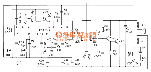
This is the schematic diagram for an automatic search FM radio. The primary component is the TDA7088 integrated circuit, which encompasses the FM radio receiver, antenna, oscillator, mixer, automatic frequency control (AFC) circuit, intermediate frequency amplifier (with an IF...
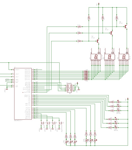
Learn to use microcontrollers to create traffic-light applications. In this project, the AVR-007 microcontroller from Circuits-Home will be utilized. Before developing the program, it is essential to understand the hardware specifications. The project focuses on developing a traffic-light control system...
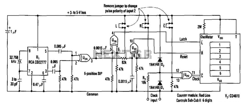
This counter facilitates the direct readout of frequency-generating equipment by incorporating a 1-Hz time base to latch, reset, and condition the count signal. The design allows for the selection of either polarity. By differentiating, inverting, and ORing the clock...
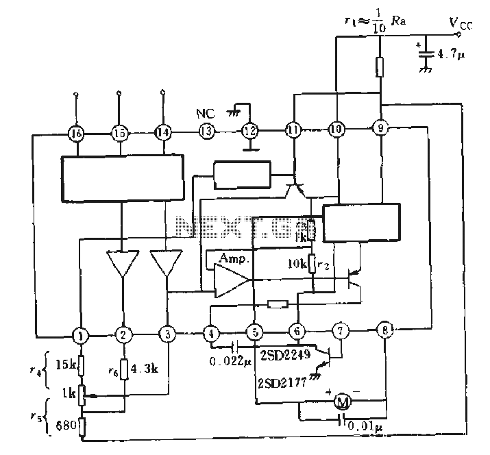
The AN6657 is a 16-pin dual in-line plastic package, while the AN6657S features a 16-pin dual flat plastic package. The speed control function operates with an internal H-bridge driver chip circuit, utilizing pins 5 and 8 for H-bridge driver...
An FM amplifier is utilized to amplify signals from an exciter in broadcast radio stations. This RF FM amplifier employs solid-state materials with a minimum gain of 9 dB. The input requirement for the FM amplifier is between 5...
Here are some schematics and information that can be difficult to locate elsewhere. If there are schematics that should be included in this collection, please feel free to reach out. The intention is to expand this collection over time,...