
Mains Voltage Detector
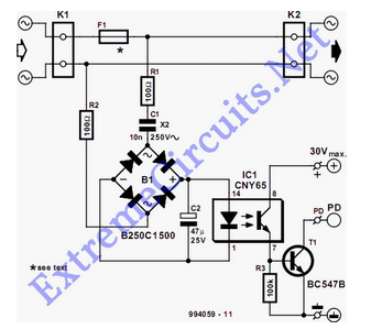
The circuit employs an optocoupler (IC1) to provide electrical isolation between the high-voltage mains supply and the low-voltage control circuitry. The primary side of the optocoupler is connected to the mains voltage through a current-limiting resistor, which ensures that the current flowing through the optocoupler's LED does not exceed its maximum rating. When an appliance is plugged into the mains, the optocoupler's LED is activated, causing it to emit infrared light.
This emitted light activates the phototransistor on the secondary side of the optocoupler. The phototransistor is configured in such a way that it can switch on or off a control signal, indicating the presence of the mains voltage. This control signal can be used to trigger other circuits, such as a microcontroller or a relay, allowing the system to respond appropriately to the detection of an appliance.
To enhance the reliability of the detection, additional components such as filtering capacitors may be included to smooth out any noise from the mains supply. Furthermore, a zener diode may be employed for over-voltage protection, ensuring that the optocoupler is not damaged by voltage spikes.
Overall, the circuit effectively provides a safe and reliable means of detecting when an appliance is connected to the mains voltage, facilitating further control and monitoring applications.The detector is intended to sense and signal to another circuit that an appliance is connected to the mains voltage. For this purpose, an optocoupler, IC1.. 🔗 External reference
Related Circuits
The circuit diagram of the variable regulator utilizes the IC L200 as a regulator for both voltage and current. This integrated circuit is produced by the company. The L200 is a versatile adjustable voltage and current regulator that can deliver...
The schematic of the power supply is illustrated below. It operates using standard household power of 120VAC at a frequency of 50/60Hz, with an adjustable output that can reach up to 25kV or higher. The power supply circuit is designed...
Power line fluctuations and cut-offs can damage electrical appliances connected to the line, particularly domestic appliances such as refrigerators and air conditioners. When a refrigerator operates at low voltage, excessive current flows through the motor, leading to overheating and...
This circuit is designed to indicate when room noise exceeds a predetermined threshold, utilizing a flashing LED to signal this condition. Three fixed noise levels are selectable: 50 dB, 70 dB, and 85 dB. The circuit employs two operational...
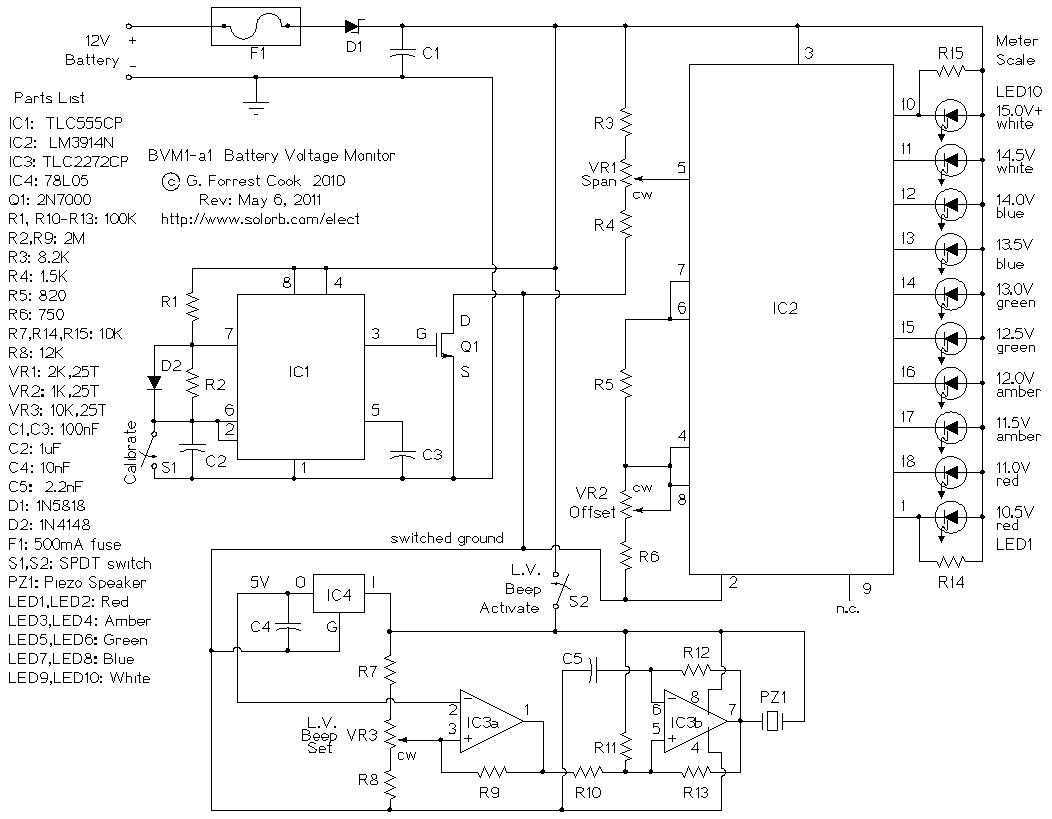
This circuit provides an audible and visual low voltage warning for 12V battery powered devices. When the battery voltage is above the set point (typically 11V), the circuit is idle. If the battery voltage should fall below the set...
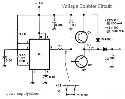
The schematic diagram originates from a 12V DC voltage doubler circuit power supply. This circuit diagram illustrates a DC voltage doubler/DC converter that transforms a 12V DC power supply into 24V DC and 18V DC outputs. It is compatible...