
mains voltage monitor
The circuit described functions as an emergency lighting solution, designed to activate in the event of a mains power failure. The core components include a mains voltage monitor, a battery power source, and an alert system comprising LEDs and a buzzer. The voltage monitor continuously checks for the presence of mains voltage. Upon detecting a loss of power, it triggers the activation of five high-intensity LEDs, ensuring sufficient illumination in dark conditions.
The power source for the LEDs is a rechargeable 9 V battery or an array of seven AA cells, providing flexibility in battery choice. The design incorporates a relay (Re1) that plays a crucial role in both charging the battery and controlling the activation of the emergency lights. When mains power is available, the relay closes, allowing current to flow through diode D8 and resistor R10. The resistor is strategically chosen to limit the charging current to a safe level, preventing damage to the battery from overcharging.
Diode D8 also prevents back-feeding of the battery voltage to the relay, ensuring that the relay is deactivated when mains power is lost. This is an essential feature for the reliable operation of the emergency lighting system. The presence of diode D6 provides a visual indication of mains power availability, serving as an additional layer of user feedback.
Once the mains power is interrupted, the relay opens, and the system switches to battery power. Integrated circuit IC1, powered by the battery, activates the JK flip-flops through the resistor R12 and capacitor C4. This activation leads to the conduction of transistors T1 and T2, which subsequently energize the five LEDs (D1-D5) and the buzzer. The buzzer serves as an auditory alert, effectively waking the user if they are asleep, thus ensuring that they are aware of the power failure.
Overall, this circuit is an efficient and practical solution for providing emergency lighting and alerting users during unexpected power outages, enhancing safety and convenience for electronics hobbyists and users alike.Many electronics hobbyists will have experienced the following: you try to finish a project late at night, and the mains supply fails. Whether that is caused by the electricity board or your carelessness isn`t really important. In any case, at such times you may find yourself without a torch or with flat batteries. There is no need to panic, as this circuit provides an emergency light . When the mains fails, the mains voltage monitor turns on five super bright LEDs, which are fed from a 9 V battery (NiCd or NiMH) or 7 AA cells. A buzzer has also been included, which should wake you from your sleep when the mains fails. You obviously wouldn`t want to oversleep because your clock radio had reset, would you When the mains voltage is present, the battery is charged via relay Re1, diode D8 and resistor R10.
D8 prevents the battery voltage from powering the relay, and makes sure that the relay switches off when the mains voltage disappears. R10 is chosen such that the charging current of the battery is only a few milliamps. This current is small enough to prevent over-charging the battery. D6 acts as a mains indicator. When the relay turns off, IC1 receives power from the battery. The JK flip-flops are set via R12 and C4. This causes T1 and T2 to conduct, which turns on D1-D5 and the buzzer. 🔗 External reference
Related Circuits
This is a simple and effective switched mode power supply (SMPS) designed to power an LCD monitor. It requires 20V at 2.3A, but the power supply unit (PSU) output voltage can be adjusted in the range of 1.2V to...
I needed a pulsating light for a certain signaling. Voltage was 230V. So I decided to make a simple circuit, consisted of a LED diode, two capacitors, two resistors, a diac and a diode. Activity of the circuit is...
This simple circuit allows for the monitoring of one's heartbeat, particularly useful during exercise. The transducer employed for pulse detection is an electronic component. This circuit typically incorporates a photoplethysmogram (PPG) sensor as the transducer to detect changes in blood...
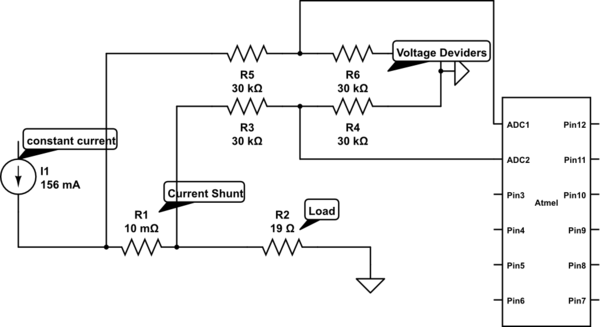
Measure current on a constant current source (LM317). Since a 3.3V chip is being used, a voltage divider is also required for reading the current. Will this circuit function correctly, or will it cause issues by attempting to increase...
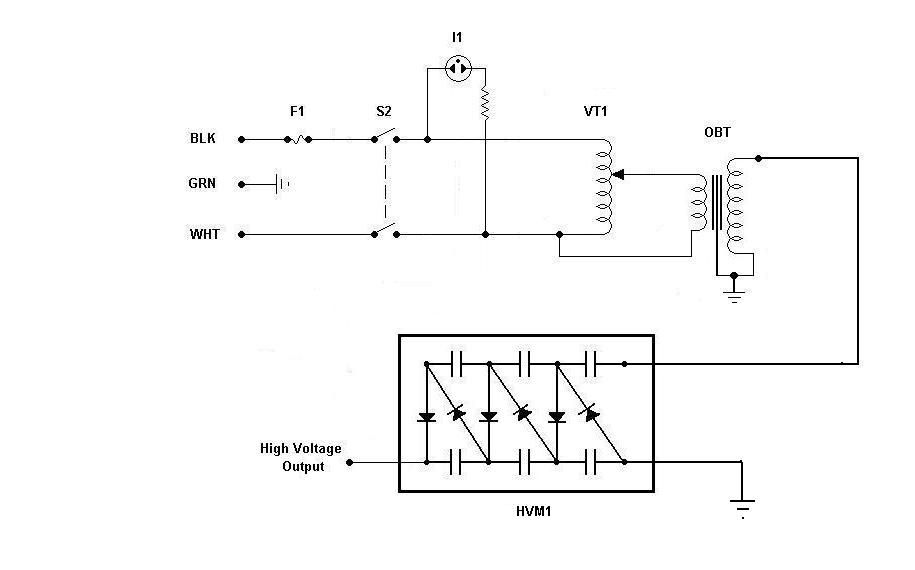
Using components from old microwave ovens, TV sets, and oil burners, it is possible to construct an economical instrument capable of producing high voltage outputs. The primary element in this setup is a voltage multiplier, which should be assembled...

This high-voltage pulse supply generates pulses up to 30 kV. Q1 and Q2 form a multivibrator in conjunction with peripheral components R1 through R6, and C1, C2, C3, C5, C6, and D2. R9 adjusts the pulse repetition rate, while...