
Make this Fancy LED Tail Ring Light Circuit for your Car
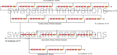
The circuit design features a serial shift register (IC1), which is pivotal for controlling the LED sequencing. The shift register operates by receiving clock pulses at pin #8, which triggers the output pins sequentially. Each activated output pin corresponds to an LED that is part of the circular arrangement. The LEDs are driven by transistors (T1, T2, T3, T4, T5), which act as switches, allowing current to flow through the LEDs when activated. The arrangement of the LEDs in a circular pattern enhances the visual effect of the light sequence, creating a dynamic and engaging display as the brake is applied.
The design can be further refined by incorporating additional features such as adjustable LED brightness, using PWM (Pulse Width Modulation) techniques, to enhance visibility during different lighting conditions. Additionally, integrating a microcontroller could allow for customizable lighting patterns and sequences, providing greater flexibility and functionality. The power supply for the circuit should be carefully considered to ensure it meets the voltage and current requirements of the LEDs while maintaining efficiency and reliability.
In summary, this LED sequencing diverging ring light circuit offers a creative solution for automotive lighting, combining aesthetics with functionality. The careful arrangement of components and thoughtful design choices contribute to an effective and visually striking tail light system.The following article describes a fancy LED sequencing/diverging ring type light which can be used as a tail brake light in cars. The circuit idea was requested by one of the avid readers of this blog, Mr. Bobby. lets learn more. Could this circuit be adapted to create a round tail light that lights rings in sequence from the center out as the bra
ke is pressed, one ring at a time until all the LEDs are lit and then flash all the LEDs twice and keep all LEDs lit solid after If not, could you design a circuit that would I would be willing to pay for your time. IC1 which is a "serial shift resistor" forms the heart of the entire circuit, the main function of this IC is to illuminate the LEDs connected to pin outs #3-4-5-6-10-11-12-13 in a sequence, keeping the sequence latched and illuminated as it proceeds.
This happens in response to each clock pulse applied at pin#8 of the IC. The LEDs which aretriggeredby the pin#3-4-5-6 and 10 are arranged as rings such that it illuminates from inner most ring first toward the outermost ring, producing an interesting and visually rich effect. In response to the above clocks, the sequence proceeds creating the desired diverging illumination effects, until it reaches pin#10.
The LEDs receive the required positive supply through T1 which stays triggered due to the low logic at pin#13 of IC1 The LEDs which needs to be connected across the collectors of T1 and T2/T3/T4/T5 may be wired up in the following manner. The arrangement should be designed in a circular manner to form the corresponding RINGs. 🔗 External reference
Related Circuits
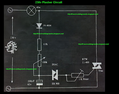
This circuit operates at 230V and can be utilized for party decoration purposes. It is sourced from an old circuit book titled "100 Circuit Book." The components include DIAC ER 900 and TRIAC BTW 11-400. The circuit is designed to...

A capacitance meter is an essential instrument for electronics hobbyists and professional electronic technicians. A capacitance meter is a specialized device used to measure the capacitance of capacitors in electronic circuits. It is a valuable tool for diagnosing and troubleshooting...

A snubber circuit consisting of R2 and C2 may be necessary, as R1 and C1 are designed for optimized triggering rather than for dV/dt protection. Fiber-optic pairs can be utilized with discrete SCRs to switch high voltages. A photonic...
This circuit is designed for children's entertainment and can be installed on bicycles, battery-powered cars, motorcycles, as well as on models and various games and toys. When switch SW1 is positioned as depicted in the circuit diagram, it generates...
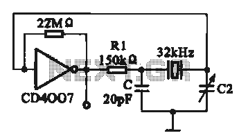
A 32 kHz clock oscillator is essential for digital circuits, as depicted in the schematic. The 32 kHz crystal clock oscillator serves to provide a time reference signal for the digital circuit. It utilizes a CMOS integrated circuit, specifically...

This DIY magnetic field sensor circuit is straightforward and capable of detecting both fixed magnetic fields and those that vary at audio frequencies. The device is not designed for precise measurement of magnetic field strength. A small and relatively...