
making of wireless car
To control one motor, two bits of information are needed, while four bits are required for two motors. The RF module utilized operates at either 433 MHz or 315 MHz ASK type. A suitable motor driver must be connected to the output of the decoder IC to drive the motors. The motor driver circuit may include a relay, a transistorized H-Bridge, or motor driver ICs such as the L293D or L298. The schematic demonstrates the use of the L293D to drive a pair of DC or geared motors. The motor supply voltage can safely reach up to 24 volts, but the IC supports a maximum current of 600 mA per channel, which is adequate for small DC geared motors. To mitigate noise in the circuitry, 0.22 µF capacitors should be added across both motors, and a 100 µF capacitor should be placed between the motor supply pin and ground. Connections M1-A and M2-B correspond to Motor 1, while M2-A and M2-B correspond to Motor 2. These control inputs can be interfaced with any logic circuitry or microcontroller.
The wireless car project combines the use of RF communication and motor control to create a remote-controlled vehicle. The RF module, typically a transmitter and receiver pair, facilitates communication between the remote control and the car. The transmitter sends control signals that are received by the receiver connected to the decoder IC. The decoder interprets these signals and translates them into control commands for the motor driver.
The motor driver, such as the L293D, is a dual H-bridge driver that allows for bidirectional control of DC motors. This enables the car to move forward, backward, and turn by controlling the polarity of the voltage applied to the motors. The L293D can control two motors simultaneously, making it suitable for this application. The motor driver is powered by an external supply, which should be within the specified voltage range to prevent damage to the IC.
The inclusion of capacitors is essential for ensuring stable operation. The 0.22 µF capacitors help filter out voltage spikes generated by the motors, which could cause interference with the RF signals. The 100 µF capacitor provides additional stability to the power supply by smoothing out fluctuations, ensuring that the motor driver receives a consistent voltage.
In summary, this wireless car project utilizes an RF module, a decoder IC, and a motor driver to create a functional remote-controlled vehicle. The careful selection of components and the inclusion of noise-reducing capacitors are critical for achieving reliable performance in the final design.Here I am going to explain you how to make a wireless car. With the advent of IC`s, it has become very simple. Some registers are also required. To make your work simpler I would recommend to go to an Electronics Shop and ask for wireless Car 413 Mhz ASK type kit*. You will find everything you require except motors and tyres. In Mumbai you will get everything on Lamington road in Grant Road. Now in order to control say one motor, we require 2 bits of information while we need 4 bits of information to control 2 motors. The RF module used here is 433/315Mhz ASK type. In order to drive motors, we need to connect a suitable motor driver at the output of the decoder IC.
The motor driver circuit can consist of a Relay, transistorized H-Bridge or motor driver ICs like the L293D, L298 etc. This schematic shows the use of L293D to drive a pair of DC motors/Geared Motors. The motor supply voltage can go up to 24Volts safely. But the IC supports a maximum of only 600mA current/channel; which is more than enough to drive small DC geared motors.
Add 0. 22uF capacitors across both the motors to reduce the effect of noise on the circuitry. We can also add 100uF capacitor between the motor supply pin and the Gnd. Connections M1-A and M2-B correspond to Motor 1 while connections M2-A and M2-B correspond to Motor 2. These control inputs can be connected to any logic circuitry or a microcontroller. 🔗 External reference
Related Circuits
This device is a simple timer that keeps the headlights of a vehicle on for approximately 1 minute and 30 seconds, allowing access to dark areas without the need to manually switch off the lights. Activating switch P1 initiates...
The transmission circuit for inductive wireless headsets must be securely mounted on a wall or ceiling, limiting its outdoor usability, which is a significant disadvantage of inductive wireless headphones. In contrast, infrared wireless headsets utilize a compact infrared transmitter...
This microphone circuit was submitted by Lazar Pancic from Yugoslavia. The sound card for a PC typically features a microphone input, speaker output, and occasionally line inputs and outputs. The microphone input is designed specifically for dynamic microphones with...
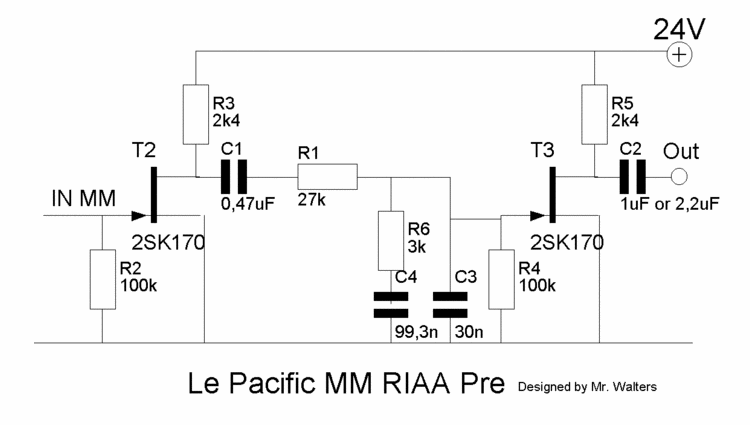
This document describes a DIY build of the Boozhound Laboratories JFET Phono Preamplifier constructed on a stripboard. The BHL preamp is primarily based on the Le Pacific RIAA phono preamplifier circuit. The construction utilizes brown polypropylene capacitors sourced from...
This circuit is designed for use with inductive pick-up elements and dynamic microphones. Most soundcards feature a line input and a separate input for electret (condenser) microphones. To connect an inductive tape recorder head or a dynamic microphone, an...
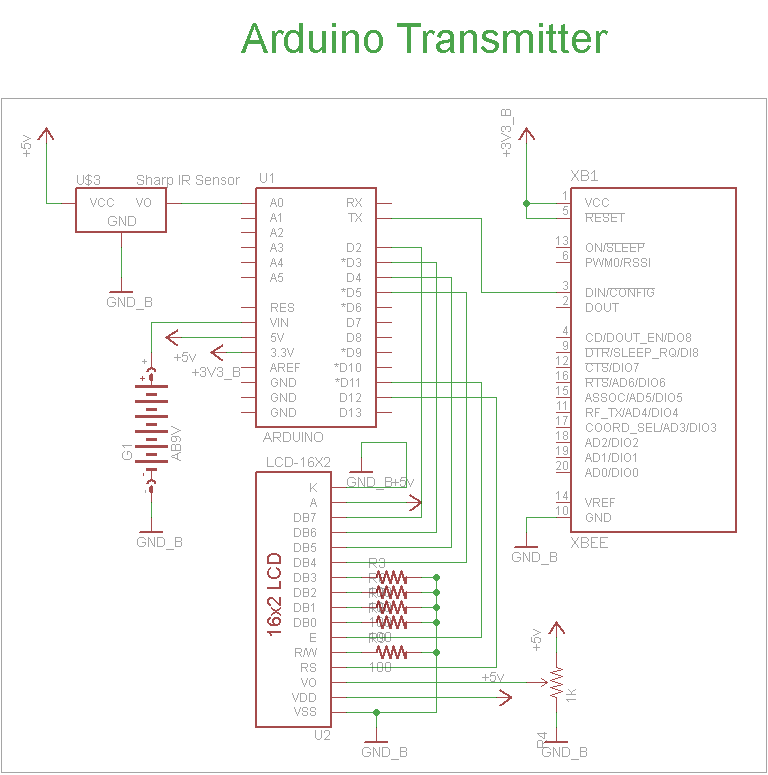
The schematic for the transmitter in this project consists of four main components: the Arduino UNO, the Sharp IR distance sensor, the XBee wireless modules, and a 16x2 LCD. The connections between these components are illustrated in the schematic....