
Marker-generator
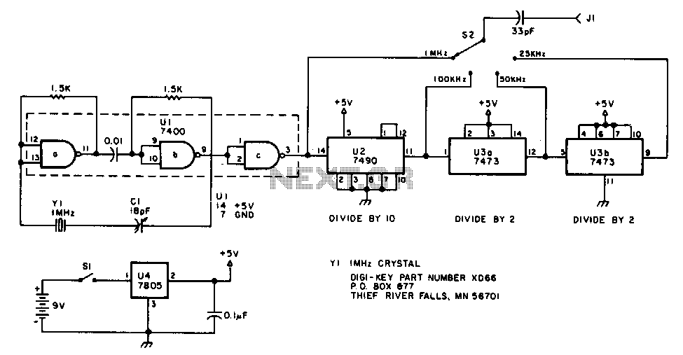
The oscillator section employs three sections of a 7400 quad NAND gate integrated circuit. The 1 MHz signal generated by the oscillator is input into a 7490 decade counter, which is configured to divide by ten, producing a 100 kHz output signal. To derive the 50 kHz and 25 kHz outputs, the 100 kHz signal is further divided by a 7473 dual J-K flip-flop. The first half of the 7473 divides the 100 kHz signal by two, resulting in a 50 kHz signal. The second half of the 7473 again divides by two, yielding a 25 kHz signal. Switch S2 selects the output, which is a square wave rich in harmonics. The generator can be powered from any suitable 6 to 12 V DC source. A 7805 fixed voltage regulator provides the regulated voltage for the oscillator and divider chips. The described generator is powered by a 9 V transistor radio battery.
The oscillator circuit is designed to create precise frequency outputs using a combination of digital logic components. The core of the oscillator utilizes three NAND gates from the 7400 series, which are configured in such a way to produce a stable 1 MHz square wave. This frequency is critical as it serves as the primary clock signal for subsequent divisions.
The 7490 decade counter is employed to reduce the frequency from 1 MHz to 100 kHz. This IC is a versatile counter that can count from 0 to 9 and is particularly useful in applications requiring frequency division. By configuring the counter to divide by ten, the 1 MHz signal is effectively divided down to 100 kHz, which is then fed into the dual J-K flip-flop, specifically the 7473 IC.
The 7473 dual J-K flip-flop operates in a toggle mode, allowing it to divide the frequency of the input signal by two. The first flip-flop stage takes the 100 kHz signal and divides it to produce a 50 kHz output. The second flip-flop stage again divides the 50 kHz signal by two, resulting in a final output of 25 kHz. The outputs from the flip-flops are square waves, characterized by their harmonic content, which can be beneficial in various applications requiring signal modulation.
To facilitate the operation of the circuit, a power supply within the range of 6 to 12 V DC is required. A 7805 voltage regulator is incorporated into the design to ensure a consistent output voltage of 5 V, which is necessary for the reliable operation of both the oscillator and the divider circuits. This regulator is capable of handling input voltages up to 35 V, making it suitable for various power supply configurations. The entire system can be conveniently powered using a standard 9 V battery, such as those used in transistor radios, providing a portable solution for generating the desired frequency outputs.
Overall, this oscillator circuit is a robust design that effectively utilizes digital logic components to achieve precise frequency generation and division, making it suitable for a variety of electronic applications.The oscillator section uses three sections of a 7400 quad NAND gate integrated circuit. The 1-MHz signal from the oscillator is fed into a 7 490 decade counter configured to divide by ten, providing the 100kHz signal. To obtain the 50 and 25kHz outputs, the 100-kHz signal is further divided by 7473 dual J-K flip-flop.
The first half of the 74 73 divides the 100-kHz signal by two, yielding the 50 kHz signal. The second half of the 7473 again divides by two, giving the 25kHz signal. S2 selects the output, a square wave, rich in harmonics. The generator can be powered from any convenient 6 to 12 Vdc source. A 7805 fixedvoltage regulator supplies the regulated voltage for the oscillator and the divider chips. The generator described here is powered by a 9-V transistor radio battery. 🔗 External reference