Master/Slave Switch
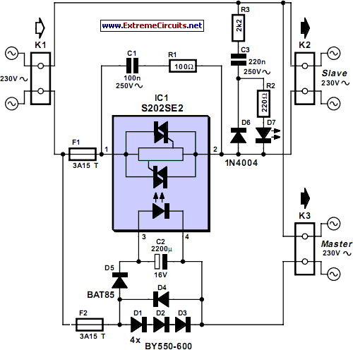
The circuit detects the mains current supplied to a master device and controls the on/off state of slave equipment. This functionality is particularly beneficial in environments such as hi-fi systems or home computers, where multiple peripheral devices can be managed simultaneously. A solid-state relay from Sharp serves as an optimal switching component for this application, featuring a built-in zero-crossing detector that ensures switching occurs only when the mains voltage is at zero, thereby minimizing any potential interference. The triac drive circuitry, including optical coupling, is integrated on-chip, resulting in very few external components and eliminating the need for an additional power supply. This contributes to a compact final design. Diodes D1, D2, D3, and D4 are responsible for current sensing and generate a voltage on capacitor C2 when the master equipment is powered on. A Schottky diode is utilized for D5 to minimize forward voltage losses. The circuit exhibits high sensitivity, capable of switching the slave device even when the master draws minimal mains current. The RC network formed by resistor R1 and capacitor C1 provides protection for the solid-state relay against voltage transients from the mains. This circuit interfaces directly with the mains supply, necessitating strict adherence to safety guidelines due to the presence of lethal voltages on the chip's pins. For safety, the LED must be installed behind a transparent plexiglass shield.
The circuit operates by monitoring the current flowing through the master device. When the master device is activated, the current sensing diodes (D1, D2, D3, and D4) detect the increase in current and generate a corresponding voltage across capacitor C2. This voltage triggers the solid-state relay, allowing current to flow to the slave devices. The integrated zero-crossing detector within the solid-state relay ensures that the relay is activated only at the moment the AC voltage crosses zero, which is crucial for reducing electromagnetic interference and ensuring a smooth operation of the connected devices.
The use of a Schottky diode (D5) is advantageous in this design as it minimizes the forward voltage drop, which enhances the efficiency of the current sensing circuit. This is particularly important in scenarios where the master device may draw very low current, ensuring reliable operation of the slave devices under varying load conditions.
The RC network, consisting of R1 and C1, serves a dual purpose: it filters out high-frequency noise and provides transient voltage suppression to protect the solid-state relay from potential damage caused by voltage spikes in the mains supply. This is critical for maintaining the longevity and reliability of the circuit.
Given that the circuit is connected directly to the mains, it is imperative to follow all safety precautions rigorously. This includes using proper insulation and ensuring that components are rated for the voltages they will encounter. The installation of the LED behind a transparent plexiglass shield not only enhances safety but also allows for visual indication of the circuit's operational status without exposing users to electrical hazards. Proper enclosure and labeling of the circuit are also recommended to prevent accidental contact with live components.The circuit senses mains current supplied to a master` device and switches slave` equipment on or off. This feature is useful in a typical hi-fi or home computer environment where several peripheral devices can all be switched on or off together.
A solid-state relay from Sharp is an ideal switching element in this application; a built-in zero crossing detector ensures that switching only occurs when the mains voltage passes through zero and any resultant interference is kept to an absolute minimum. All of the triac drive circuitry (including optical coupling) is integrated on-chip so there are very few external components and no additional power supply necessary. This makes the finished design very compact. Diodes D1, D2, D3 and D4 perform the current sensing function and produce a voltage on C2 when the master equipment is switched on.
A Schottky diode is used for D5 to reduce forward voltage losses to a minimum. The circuit is quite sensitive and will successfully switch the slave even when the master equipment draws very little mains current. The RC network formed by R1 and C1 provides some protection for the solid-state relay against mains-borne voltage transients.
This circuit is connected to the mains. it is important to be aware that the chip has lethal voltages on its pins and all appropriate safety guidelines must be adhered to! This includes the LED, for safety it must be fitted behind a transparent plexiglass shield. 🔗 External reference
